
| Tweet |

Custom Search
|
|

|
||
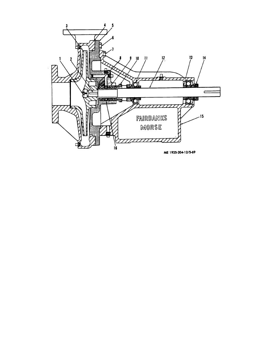 1.
Impeller screw
9.
Pocking
2.
Impeller key
10.
Packing gland
3.
Impeller
11.
Inner bearing
4.
Casing
12.
Shaft
5.
Back head
13.
Thrust bearing
6.
Capscrew
14.
Bearing lock
7.
Capscrew
15.
Pump frame
8.
Impel ler shaft sleeve
16.
Seal cage
Figure 5-69. Bilge and ballast pump.
(3) Remove impeller screw (1) from shaft (12).
(8) Remove bearing lock from inner bearing (11) by
(4) Remove impeller (3).
removing setscrew in bearing lock and withdrawing from
shaft.
(9) Withdraw inner bearing from shaft and pump frame.
NOTE
(10) Remove thrust bearing (13) in the same manner as
Impeller is keyed to shaft: when
the inner bearing.
withdrawing impeller from shaft note the
d. Cleaning, Inspection, and Repair.
key positions.
(1) Clean inner bearing and thrust bearing with a
cleaning solvent which meets requirements of FED SPEC P
(5) Remove nuts which hold packing gland (10) against
D-680.
packing (9) and withdraw packing gland.
(2) Inspect the bearings for wear. If worn, replace.
(6) Remove capscrews (7) and withdraw back head from
(3) Inspect impeller shaft sleeve (8) for wear. If worn.
shaft and pump frame (15).
remove from shaft by heating surface of sleeve. Replace with
(7) Withdraw packing gland from shaft.
new sleeve.
Change 1
5-91
|
||
|
||


