
| Tweet |

Custom Search
|
|

|
||
 (5) Keep commutator clean.
(2) Replace bolts securing pump to foundation.
(3) Adjust belt so that it has 1-inch horizontal slack at a
b. Removal
point midway between the two pulleys.
(1) Disconnect external wiring from motor connection
(4) Tighten mounting bolts.
box, and mark for assembly.
(2) Remove bolts holding coupling flanges together.
(3) Loosen mounting bolts and lift motor from
5-34. Motor
foundation.
a. Maintenance and Adjustment (TM 55-506).
c. Disassembly.
(1) Lubricate in accordance with LO 55-1925-204-12.
(1) Remove brushes from holders; disconnect wiring
(2) Inspect brushes. Replace brushes worn to one-half
from brush holders and mark for assembly.
normal length. Sand new brushes to contour of commutator.
(2) Remove coupling half and key from shaft.
(3) Check brush spring tension. Adjust tension to 1 3/4
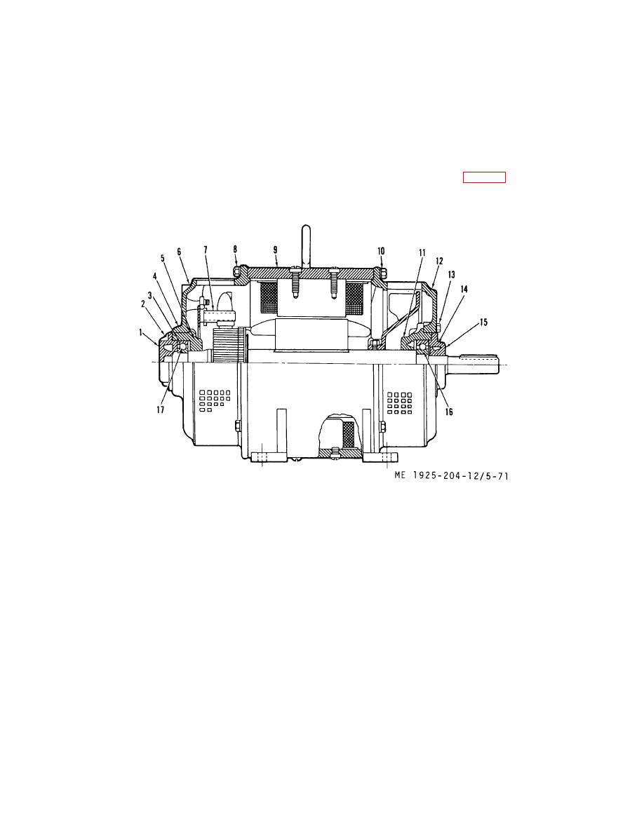
(3) Loosen setscrew (4, fig. 5-71) in commutator endbell.
to 2 1/2 psi at contact surface.
(4) Check brushes to see that they move freely in
holders.
1.
Bearing housing outer
10.
Bolt, mounting
2.
Screw
11.
Hearing housing [inner)
3.
Gasket
12.
Drive endbell
4.
Setscrew
13.
Capscrew
5.
Bearing housing (inner)
14.
Screw
6.
Commutator endbell
15.
Rearing housing (outer)
7.
Brush stud
16.
Ball bearing
8.
Bolt
17.
Ball bearing
9.
Bilge frame me
Figure 5-71. Bilge and ballast pump motor.
(4) Remove commutator endbell mounting bolts (8) and
(5) Remove drive and endbell mounting bolts (10), and
pull commutator endbell (6) from field frame and bearing
withdraw armature and endbell assembly carefully from field
housing assembly
frame.
5-94
|
||
|
||


