
| Tweet |

Custom Search
|
|

|
||
 (6)
Connect motor electrical connections.
(2)
Pack ball bearings with grease in accordance
with applicable lubrication order prior to installation of outer
bearing cap.
5-44. Controller
(3)
If a new brush holder is installed, position in
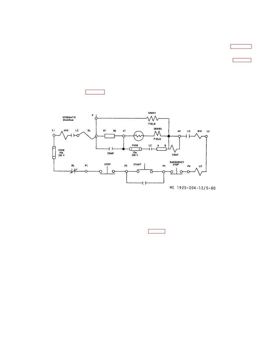
a General. The fuel oil transfer pump controller is a dc
groove and set brush angle to correspond with angel of
magnetic type with current limit acceleration. Depressing the
original holders.
START button energizes the line contact (fig.
(4)
If new brushes are installed, sand to contour of
connecting the motor and the series resistors across the line.
commutator (TM 55-506).
The coil of the counter electro-motive force contactor is
(5)
Adjust brush tension to approximately 2 psi of
connected across the motor armature. The CEMF (fig. 5-80)
contact surface.
contactor is set to pick up at approximately 70 percent of line
f. Installation.
voltage across the armature as the motor accelerates; the
(1)
Place motor on mounting with motor shaft in line
voltage across the armature gradually builds up until it
with pump shaft.
reaches 70 percent line voltage, at which time the CEMF
(2)
Move motor toward pump to engage clutch.
contactor closes; its contacts short out the starting resistors
(3)
Install motor mounting bolts and tighten.
(R1-R2) and connect the motor directly across the line.
(4)
Check coupling alignment (fig. 5-79).
(5)
Rotate shaft by hand to check for binding.
Figure 5-80. Controller, fuel oil transfer pump motor, schematic diagram.
(6)
Remove accumulation of carbon from arc
b. Maintenance.
shields.
(1)
Keep interior of controller enclosure clean.
(7)
Check operation of line contactor and
(2)
Wipe magnetic sealing surfaces clean.
accelerating contactor (d and e below).
(3)
Do not lubricate contact tips.
(4)
Check tightness of all connections. Particularly
c. Overload Relay.
the connection to overload heater connections.
(1)
To replace heater, remove screw and washer
(5)
Inspect contacts for excessive burning. Remove
(13, fig. 5-81) from each end of heater and lift off heater unit.
excessive roughness from copper contacts with a fine file. Do
Install new heater in reverse order of removal and tighten
not file silver contacts. Replace contacts when worn to one-
screws securely.
half original thickness.
5-108
|
||
|
||


