
| Tweet |

Custom Search
|
|

|
||
 TM 55-1925-204-12
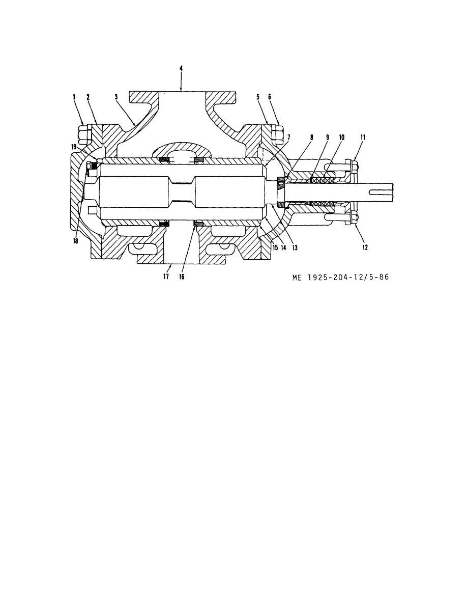
1. Capscrews
11.
Packing gland nut
2. End cover
12.
Packing gland
3. Pump housing
13.
Power rotor
4. Suction inlet
14.
Idler rotor
5. Packing gland end cover
15.
Rotor housing
6. Capscrews
16.
Housing spacer ring
7. Idler rotor
17.
Discharge outlet
8. Bushing
18.
Adjusting nut
9. Packing washer
19.
Locknut
10. Packing
Figure 5-86. Lubricating oil standby pump, section.
(3) Withdraw power rotor (13) and idler rotors (7
(1) Assemble
pump
in reverse order of
and 14) from the rotor housing (15).
disassembly leaving packing out until pump is assembled.
(4) Loosen packing gland nuts (11) and swing bolt
(2) Adjust idler rotor adjusting nuts to give rotors a
out of way.
slight pressure against packing gland end cover.
(5) Withdraw packing gland from pump housing
NOTE
and remove worn packing.
Do not overtighten; to do so will warp idler
(6) Remove capscrew (6) and packing gland end
rotors causing distortion of rotor housing
cover from pump housing.
bores.
(7) Remove bushing (8) from packing gland end
(3) Replace packing with same amount and type as
cover.
removed.
g. Cleaning, Inspection, and Repair.
(4) Adjust packing gland nuts (11) finger tight.
(1) Examine power rotor bushing and power rotor at
i. Installation.
point where rotor revolves in bushing. If bushing shows signs
(1) Install coupling cover on pump shaft and slide
of wear or score marks, replace bushing.
coupling into position on shaft.
(2) Remove all traces of old gasket from both end
(2) Position pump assembly on foundation and bolt
covers.
in place.
h. Assembly.
5-115
|
||
|
||


