
| Tweet |

Custom Search
|
|

|
||
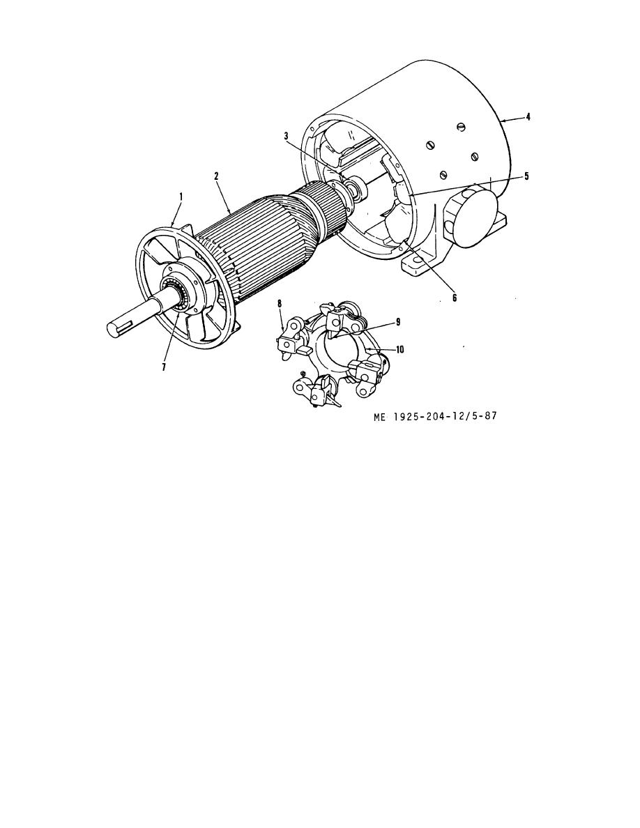 1.
Fan
6. Field main
2.
Armature
7. Bearing fan end
3.
Bearing, front end
8. Brush holder
4.
Motor frame
9. Brush
5.
Field, interpole
10. Brush assembly
Figure 5-87. Motor, lubricating oil standby pump drive.
(5) Remove brush assembly (10) from frame.
(4) Inspect commutator for grooving or burring. If
(6) Remove capscrews holding bearing caps to
commutator cannot be smoothed by taking a light cut in a lathe,
endbells and remove bearing cap and endbells.
replace armature.
(7) Withdraw bearing from endbell.
(5) Check bearings for roughness by rotating by
(8) Disconnect brushes (9) from brush assembly
hand; replace defective bearings.
(10); release brush spring and lift brush from brush holder (8).
f. Assembly.
e Cleaning, Inspection, and Repair.
(1) Assembly is in reverse order of disassembly.
(1) Blow loose dirt and carbon from windings with
(2) Pack new bearings with lubricant in accordance
clean, dry, low-pressure air.
with LO 55-1925-204-12-7.
(2) Wipe all parts clean using cloth moistened with
(3) Adjust brush tension. Replace brush springs
drycleaning solvent in conformance with FED SPEC P-D-680.
that cannot be adjusted to proper tension.
(3) Inspect windings tor evidence of short-circuit or
(4) Replace coupling cover and position coupling
damaged insulation. If armature windings are detective, replace
half in same location from which removed.
armature. If field windings are defective, replace motor.
g. Installation.
(1) Using chainfall, set motor in place on
foundation.
5-117
|
||
|
||


