
| Tweet |

Custom Search
|
|

|
||
 TM 55-1925-273-10-1
OPERATOR'S MANUAL
INLAND AND COASTAL LARGE TUG (LT)
LOCATION AND DESCRIPTION OF MAJOR COMPONENTS
01 LEVEL INTERIOR
01 LEVEL INTERIOR
3
6
4
3
1
8
2
7
5
7
9
10 11
12
UP
DN
13
11 25 24 23 22 21
20
7
19 18
15
16
14
1
3 17
7 21
26
FWD
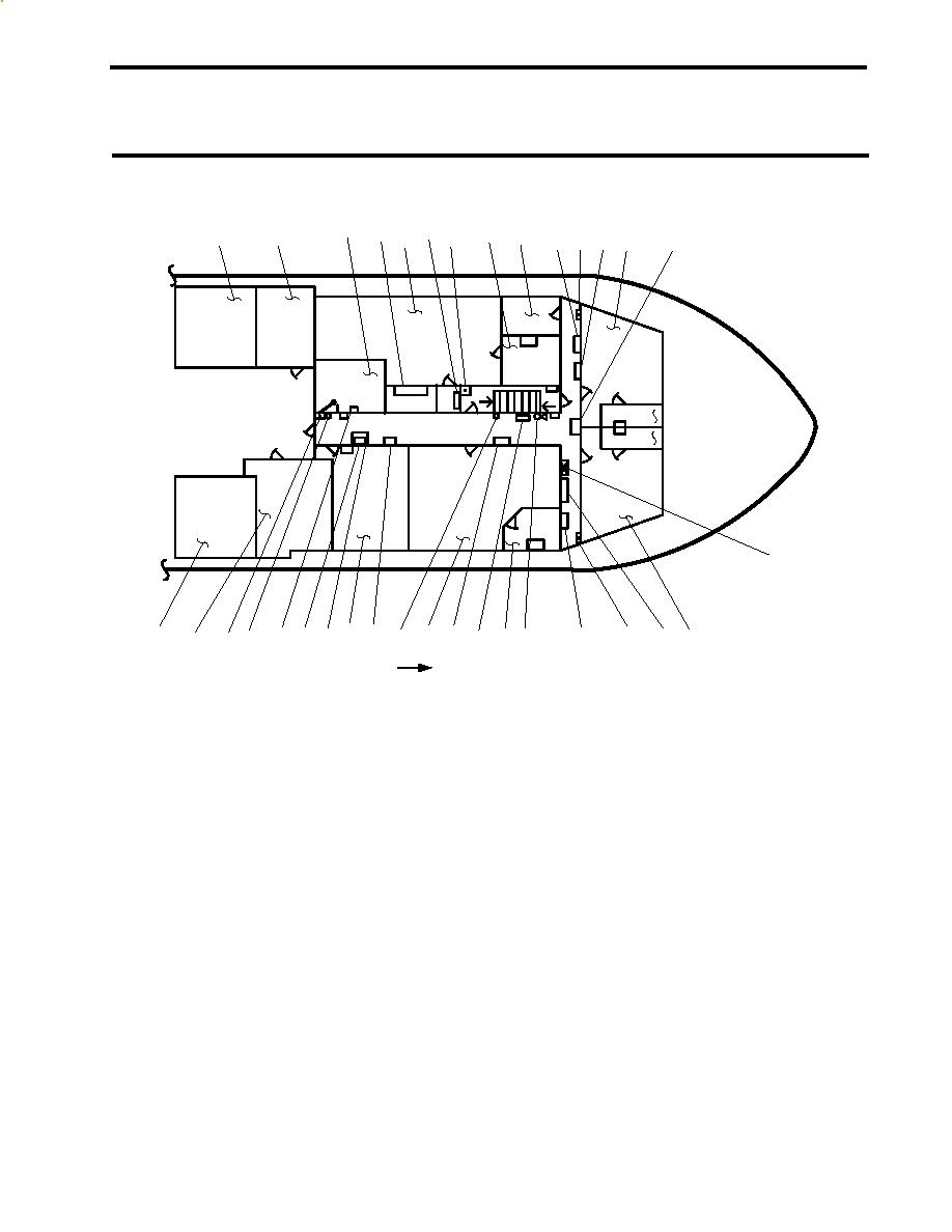
Figure 1. 01 Level Interior
1.
2.
Aft fan room (figure 1, item 2). The aft fan room contains Heating, Ventilation, and Air Conditioning (HVAC) and
electrical equipment. See figure 2 for details.
3.
Sanitary Space (figure 1, item 3). This space contains sanitary facilities, including a water closet, a sink, and a shower.
4.
Medical locker (figure 1, item 4). The medical locker provides storage space for medical supplies.
5.
Officer's stateroom 2 (figure 1, item 5). The officer's stateroom 2 provides accommodations for four officers. See
figure 3 for details.
6.
120V pilothouse emergency distribution panel (figure 1, item 6). This panel provides 120 volts to various navigation system
components, the windscreen elements, the intercom system, and the port and starboard search light power supplies.
7.
Fire alarm pull station (figure 1, item 7). This fire alarm pull station immediately alerts the crew to the presence of fire
when the lever is pulled.
8.
Forward fan room (figure 1, item 8). The forward fan room contains HVAC and electrical equipment. See figure 4 for
details.
0008 00-1
|
||
|
||


