
| Tweet |

Custom Search
|
|

|
||
 TM 55-1925-273-10-1
0008 00
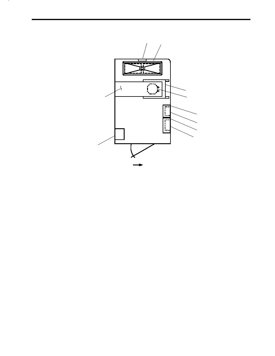
FAN ROOM 01 LEVEL (AFT)
1
2
3
10
4
5
6
7
8
9
FWD
Figure 2. Fan Room 01 Level (Aft)
1.
Ventilation fan (figure 2, item 1). This fan removes heat and gases from the battery bank.
2.
Battery bank (figure 2, item 2). The battery bank contains two 12 V batteries connected in series to provide emergency
24 Vdc power to various communication and navigation systems.
3.
Power supply (figure 2, item 3). The power supply provides power to various 24 Vdc communication and navigation
systems, and charges the battery bank.
4.
Transformer (figure 2, item 4). The 440V/120V transformer provides 120V power for various communication and
navigation systems.
5.
60 amp disconnect switch (figure 2, item 5). This switch disconnects the power supply (figure 2, item 3).
6.
HVAC SYSTEM CONTROLLER FOR RHTR 01-32-2 (figure 2, item 6). The controller turns the reheater ON and
OFF.
7.
200-amp disconnect switch (figure 2, item 7). This switch disconnects the battery bank.
8.
HVAC SYSTEM CONTROLLER FOR PRHTR 01-31-2 (figure 2, item 8). This controller turns the preheater ON and
OFF.
9.
Preheater (figure 2, item 9). The preheater warms the outside air being drawn into the fan coil unit.
10. Fan coil assemblies for the main deck and the 01 and 02 levels (figure 2, item 10). The fan coil assembly heats and cools
the interior spaces on the 01 level. It also provides a portion of the pilothouse heating and cooling.
0008 00-3
|
||
|
||


