
| Tweet |

Custom Search
|
|

|
||
 TM 55-1925-273-10-1
0011 00
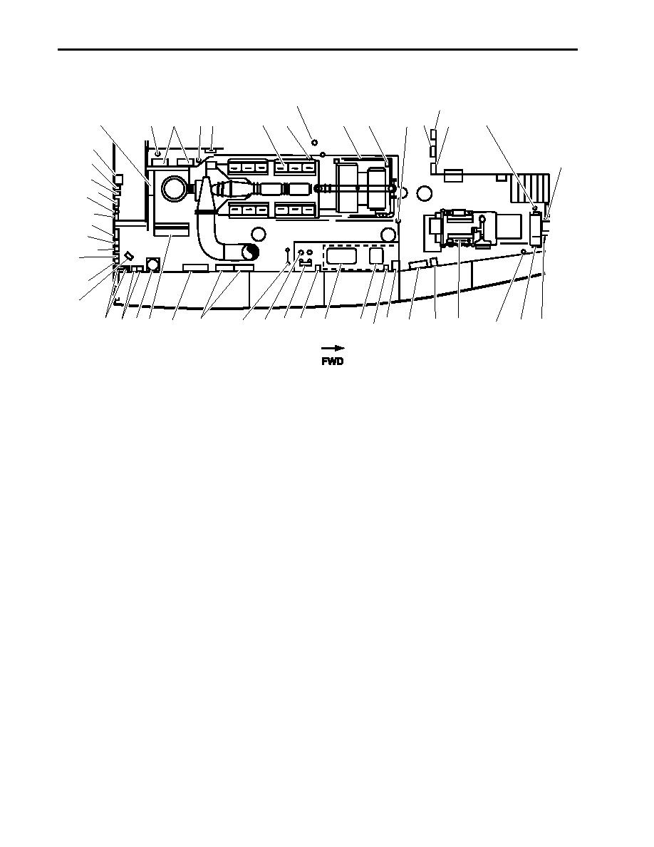
ENGINE ROOM, STARBOARD SIDE
8
12
4
1
11
7
2
3
4 5
6
10
13
14
9
45
44
15
43
42
4
41
40
39
8
38
37
36
24 23 22
19
27 26
35 34 33 32
25
30
20
17
16
31
28
21
29
18
Figure 3. Engine Room, Starboard Side
1.
Shaft brake panel 1 (figure 3, item 1). This panel provides control for the starboard shaft brake.
2.
Lube oil hand pump (figure 3, item 2). The lube oil hand pump pumps lube oil from the reduction gears to the oily waste
system.
3.
Reduction gear cooling pumps (figure 3, item 3). The reduction gear cooling pumps are electric pumps that circulate
cooling water for the reduction gears.
4.
Fire extinguisher (figure 3, item 4). The fire extinguisher is used to extinguish small fires.
5.
Fire alarm pull station and reduction gear 1 and 2 fresh water cooling pump pressure gauges (figure 3, item 5). The fire
alarm pull station is used to activate the fire alarm. The cooling pump pressure gauges indicate the pressure of the
reduction gear coolant.
6.
Main engine 1 (figure 3, item 6). Main engine 1 is an air-started, fresh water-cooled main propulsion engine. Main
engine 1 rotates clockwise when viewed from the flywheel.
7.
General alarm bell (figure 3, item 7). The general alarm bell sounds a general alarm, indicating various conditions and
emergencies.
8.
General alarm light (figure 3, item 8). The general alarm light illuminates indicating various conditions and emergen-
cies.
9.
Engine control panel (figure 3, item 9). The engine control panel houses controls and status displays for the main
engines.
10. Engine alarm horn (figure 3, item 10). The engine alarm sounds the engine alarm, indicating various conditions and
emergencies.
0011 00-6
|
||
|
||


