
| Tweet |

Custom Search
|
|

|
||
 TM 55-1925-273-10-1
0026 00
AIR COMPRESSOR
COMPRESSION
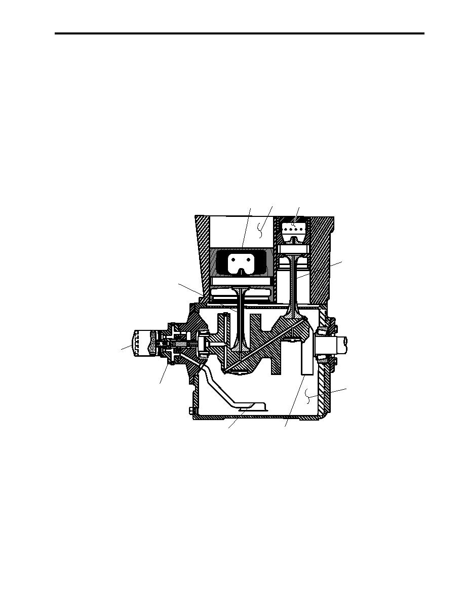
The compressor's crankshaft (figure 2, item 1) is turned by an electric motor, via a V-belt drive. As the crankshaft turns, the
pistons move up and down. During the downstroke of the low-pressure piston (figure 2, item 2), air is drawn through an
intake valve in the head of the compressor into the low-pressure cylinder (figure 2, item 3). During the upstroke of the
piston, this air is compressed.
The air that was compressed by the low-pressure piston (figure 2, item 2) is then released through a discharge valve in the
head of the compressor to a finned tube intercooler where the heat resulting from compression is allowed to dissipate. The
cooler compressed air is then drawn into the high-pressure cylinder by the downstroke of the high-pressure piston (figure 2,
item 4). On the upstroke of the high-pressure piston, the air is further compressed before being discharged through a
discharge valve in the compressor head. At this point, the compressed air enters the vessel's compressed air piping system
enroute to the starting air receivers.
3
2
4
9
9
8
6
5
1
7
Figure 2. Air Compressor
LUBRICATION
The air compressor is pressure lubricated. The moving parts within the crankcase (figure 2, item 5) are supplied with
lubrication by a positive displacement, gerotor type oil pump (figure 2, item 6). Oil is drawn up from the bottom of the
crankcase to the oil pump through an oil sump strainer screen (figure 2, item 7). The oil is then forced under pressure
through the oil filter (figure 2, item 8). After being filtered, the oil travels under pressure through drilled journals in the
crankshaft (figure 2, item 1) and connecting rods (figure 2, item 9) to lubricate crankshaft bearings, wrist pin bearings, and
the cylinder walls.
0026 00-3
|
||
|
||


