
| Tweet |

Custom Search
|
|

|
||
 TM 55-1925-273-10-1
0029 00
SEE
A
B
SHEET 1
35
40
45
50
55
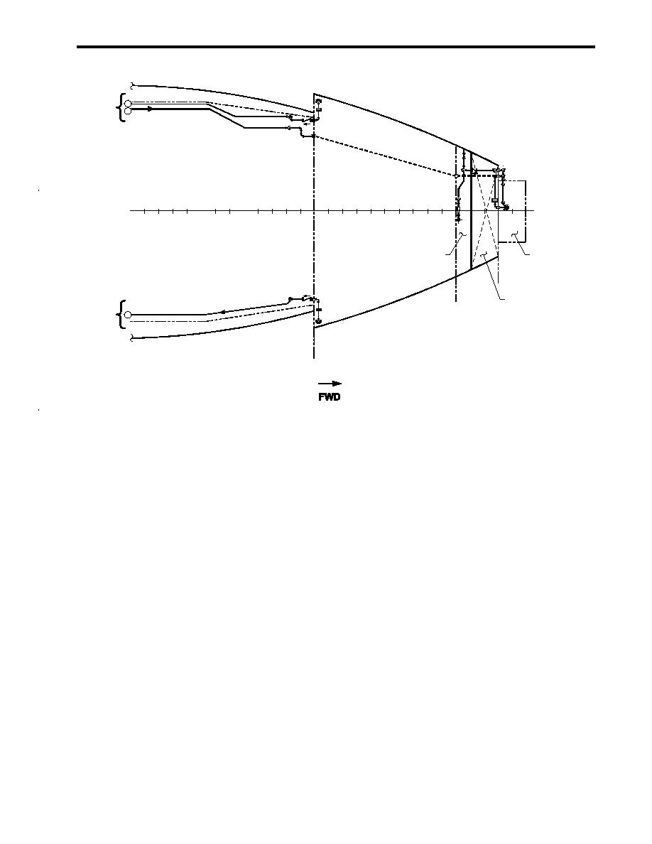
BOW THRUSTER
CHAIN LOCKER
COMPARTMENT
BALLAST TANK 1
BHD 54
SEE
C
SHEET 1
BHD 44
Figure 1. Bilge and Ballast Systems (Sheet 2 of 2)
OILY WASTE STORAGE TANK
The oily waste storage tank (figure 2, item 2) provides a holding tank that supplies oily water to be processed by the OWS
(figure 2, item 4). The oily waste storage tank also receives the oil output from the OWS. When appropriate, the oily waste
discharge pump (figure 2, item 3) can empty the oily waste storage tank through the shore connection (figure 2, item 5).
OILY WASTE DISCHARGE PUMP
The oily waste discharge pump (figure 2, item 3) is an air powered diaphragm pump. The compressed air used to drive the
pump is provided by the ship's service air system. The oily waste discharge pump's suction can be directed to either the
piping system or the oily waste drain tank (figure 2, item 1). The oily waste discharged pump's suction can also be used for
removing oily water from the bilges and to transfer the contents of the oily waste drain tank or the oily waste storage tank
(figure 2, item 2) or to a shore connection.
OIL WATER SEPARATOR
The OWS (figure 2, item 4) separates and removes oil from bilge water. Two outputs from the OWS are provided. Power
is supplied to the OWS from the main switchboard. The oil-water separation is accomplished in two stages.
The inlet baffle redirects the flow of oil droplets away from the upper coalescer bed. The inlet weir separates the oil
accumulated in the tank from the inlet flow. Oil droplets that flow past the inlet baffle accumulate on the polypropylene
granules (beads) in the coalescer beds. The polypropylene granules attract oil and repel water (oleopylic-hydrophobic),
allowing water to flow through while the oil remains are temporarily trapped in the coalescer granules. The lower coalescer
bed functions like the upper coalescer bed but is thinner and acts like a polishing bed. The water space between these beds
isolates them, preventing contamination of the lower by the upper. The clarified effluent, having passed through both
coalescer beds, is drawn through the outlet in the OWS's (figure 2, item 4) bottom.
0029 00-3
|
||
|
||


