
| Tweet |

Custom Search
|
|

|
||
 TM 55-1925-273-10-1
0032 00
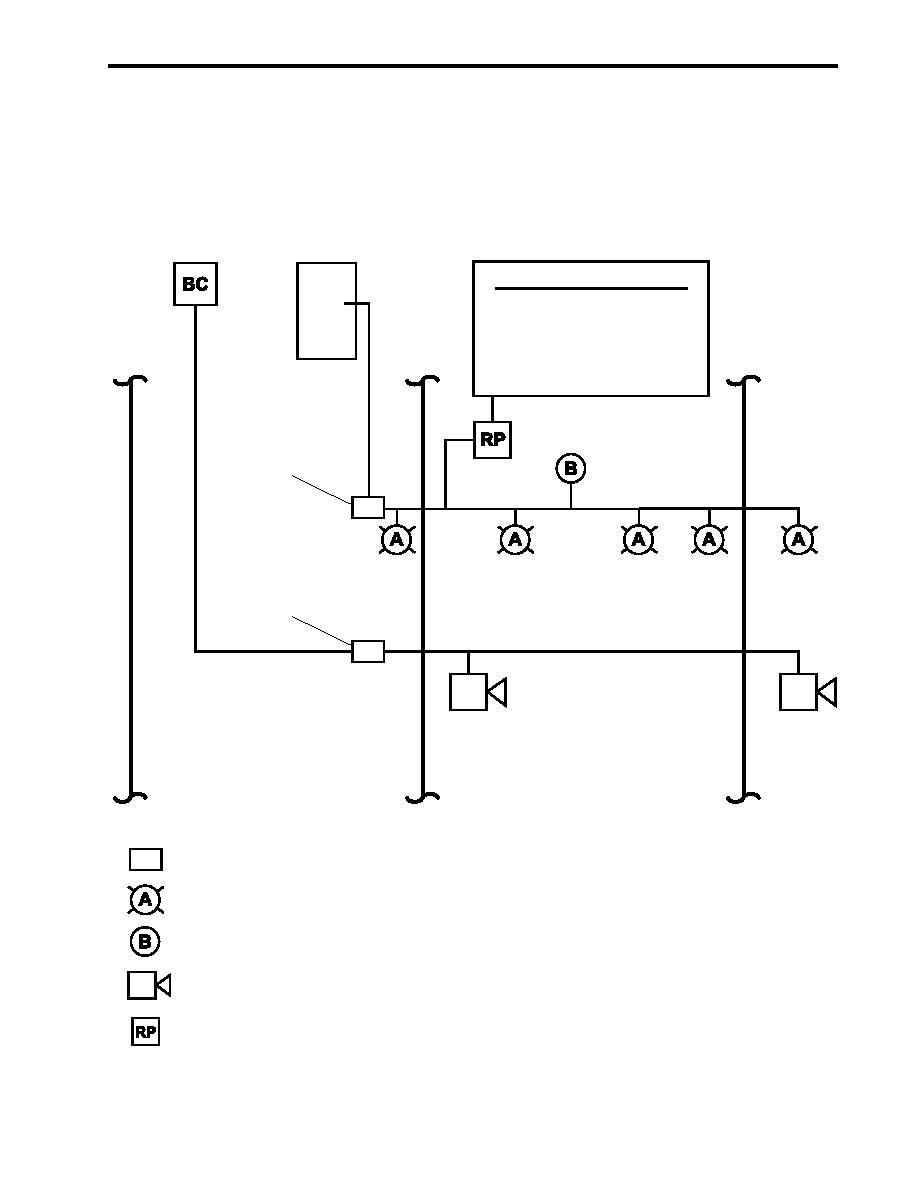
The strobe lights and bell are powered by 120V emergency lighting panel No. 1 via pressure switch PS-1 (figure 6, item 1).
The fire suppression alarm system has two horns. One horn is mounted in the engine room and the other in AMS 1. The
horns are powered by the emergency generator battery charger circuit via pressure switch PS-1A (figure 6, item 2). As
illustrated in figure 6, the use of two separate power sources provides greater assurance that personnel in the hold level will
be warned if the FM-200 fire suppression system is activated.
Emergency Lighting
Emergency Generator
PANEL 1
Battery/Charger
(Less/Recreation Space)
Equipment Shutdowns
115 Vac
Engine Room Supply Fans 1 & 2
Engine Room Exhaust Fans 1 & 2
24 Vdc
SSDG 1 & 2
Bow Thruster Engine
Firefighting Pump Drive Engine
AMS 1 Supply Fan
Fuel Oil Transfer Pumps 1 & 2
1
PS1
2
PS1a
AMS 2
ENGINE ROOM
AMS 1
Pressure Switch
PS
Amber Strobe
Bell
Electric Horn
Relay Panel Box
Figure 6. Fire Suppression Alarm System Schematic
0032 00-5
|
||
|
||


