
| Tweet |

Custom Search
|
|

|
||
 TM 55-1925-273-10-1
0039 00
7
4
5
6
3
2
1
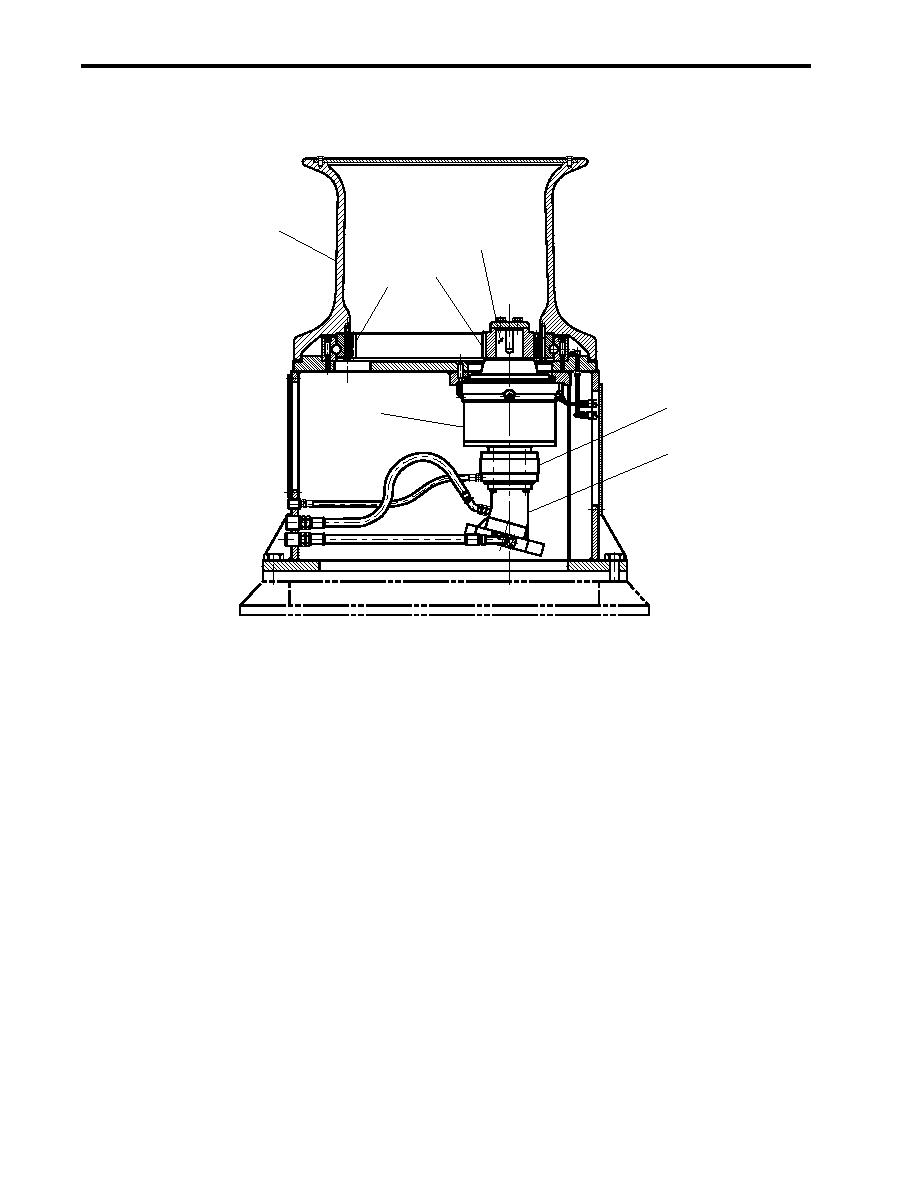
Figure 7. Capstan Mechanical Operation
ANCHOR WINDLASS
During operation under usual conditions, the anchor windlass is powered by the central hydraulic system.
Supply pressure comes into the anchor windlass control valve (figure 8, item 1) through a flow control valve (figure 8, item 2).
The flow control valve is set to permit 11 gal/min (42 L/min) to enter the anchor windlass control valve. This prevents overspeed
operation of the anchor windlass.
The anchor windlass control valve (figure 8, item 1) is comprised of a HIGH/LOW speed selector valve (figure 8, item 3),
a directional control valve (figure 8, item 4), and a counterbalance valve (figure 8, item 5).
When the HIGH/LOW speed selector valve (figure 8, item 3) is in the LOW speed position, pressure is removed from the
two speed pilot valve (figure 8, item 6) that removes pressure from the pilot port (figure 8, item 7) of the anchor windlass
motor (figure 8, item 8). When pressure is removed from the pilot port, the anchor windlass motor is in the Low Speed, High
Torque (LSHT) mode. When the HIGH/LOW speed selector valve is in the HIGH position, pressure is applied to the two
speed pilot valve that supplies pressure to the pilot port of the anchor windlass motor. When pressure is applied to the pilot
port, the anchor windlass motor shifts into High Speed, Low Torque (HSLT) mode. In this mode, the anchor windlass motor
speed is roughly doubled and torque roughly halved.
0039 00-12
|
||
|
||


