
| Tweet |

Custom Search
|
|

|
||
 TM 55-1925-273-10-1
0039 00
TOWING MACHINES
HYDRAULIC/MECHANICAL OPERATING THEORY
Under operation under usual conditions, the towing machines are powered by the towing machine hydraulic system. Hy-
draulic fluid flows to and from the towing machines (figure 5, sheet 1, item 14; figure 5, sheet 2, item 15) by the supply
(figure 5, sheet 1, item 19) and return (figure 5, sheet 2, item 20) lines. Once at the towing machines, the hydraulic flow is
controlled by the manually operated local controls, or by solenoid operated remote control valve. Hydraulic power oper-
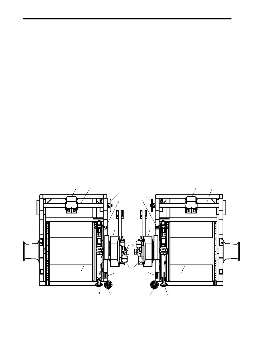
ates the hydraulic motors (figure 12, item 1) and the hydraulic brake cylinders (figure 5, sheets 1 and 2, item 21; figure 12,
item 2). All other operations are controlled mechanically.
When the manual or remote control valve directs hydraulic flow to the hydraulic motor (figure 12, item 1), pressure is also
applied to release the hydraulic brake cylinders (figure 5, sheet 1, item 21; figure 12, item 2). The main shaft then rotates in
the desired direction as decided by the direction of hydraulic fluid flow. If the operator desires the drum (figure 12, item 3)
to rotate when the main shaft rotates, the clutch band brake must be applied. See the paragraph below for an explanation of
this brake.
In addition to the hydraulic braking described above, both a clutch band brake and an auxiliary brake assembly are installed.
The clutch band brake is operated by the outboard control handle (figure 12, item 4) and the auxiliary (figure 12, item 5)
brake is operated by the inboard control handle. The auxiliary brake provides primary braking for the drum (figure 12, item
3). It brakes nothing else. The clutch band brake's primary function is to lock the drum to the main shaft. Its secondary
function is as a brake for the drum.
In order to lock the drum (figure 12, item 3) to the main shaft, the clutch brake lining acts on the surface of the outer (orbit)
gear assembly of a planetary reduction gear. When the sun gear (figure 13, item 1), which is attached to the main shaft
(figure 13, item 2) rotates, the planet gears (figure 13, item 3) rotate, too. If the orbit gear (figure 13, item 4) is held
stationary, in this case by the clutch band brake, the carrier (figure 13, item 5) will rotate in the same direction as the main
shaft, but at a lower speed. In the towing machine, the carrier is attached directly to the drum (figure 12, item 3), so carrier
rotation equals drum rotation. If the main shaft is held stationary by the hydraulic brake, the clutch band brake acts as a drum
6
7
6
7
8
8
11
11
1
1
10
2
9
9
3
3
5
4
5
4
Figure 12. Towing Machine Mechanical Operation
0039 00-20
|
||
|
||


