
| Tweet |

Custom Search
|
|

|
||
 TM 55-1925-273-10-1
0041 00
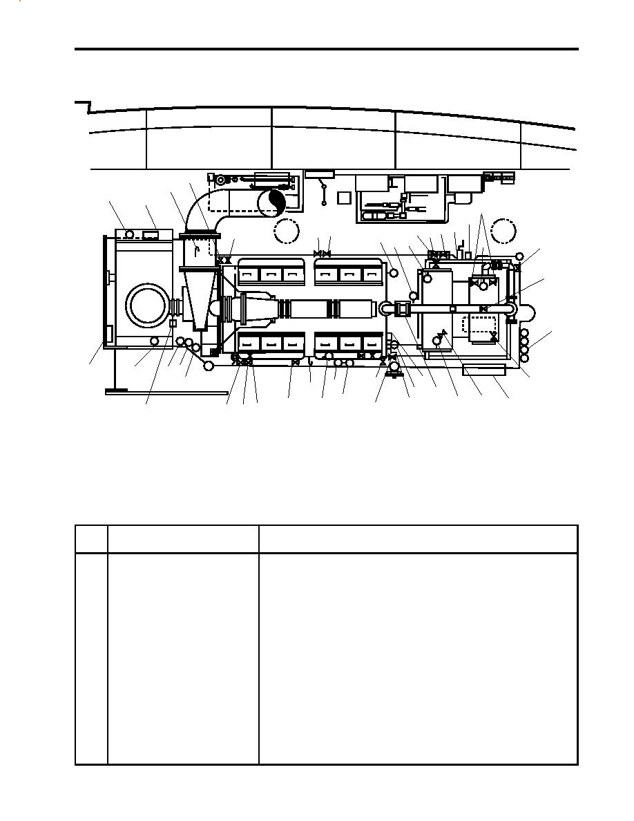
MAIN ENGINE 2 OPERATOR CONTROLS AND INDICATORS, GENERAL ARRANGEMENT
4
3
1
2
17
16
12 13 14 15
7 8
5, 6
9
10 11
18
19
20
21
42 41
45
44
27
22
40
31
33
35
28
26
32
25
24
34
23
36
29
38 37
30
39
43
Figure 11. Main Engine 2, General Arrangement
Table 11. Main Engine 2 Operator Controls and Indicators, General Arrangement (refer to figure 11)
Key
Control/Indicator
Function
1
Pressure Gauge, Shaft Brake
This gauge indicates the pressure applied to the shaft brake.
2
Shaft Brake Cylinder
This cylinder controls the shaft brake. See figure 9 for details.
3
Dipstick
This tool indicates the oil level for reduction gear 2.
4
De-4, M.E. No. 2. EXH. DR.
This valve drains condensation from main engine 2's exhaust when OPEN.
Valve
5
Cutoff Valve, Jacket Water
This valve secures the flow of engine coolant to the aftercooler.
to Aftercooler
6
Cutoff Valve, Aftercooler Drain
This valve permits draining of engine coolant from the aftercooler.
7
De-6, S.S.D.G. No. 2 EXH.
When OPEN, this valve drains condensate from the SSDG 2 exhaust.
DR. Valve
0041 00-15
|
||
|
||


