
| Tweet |

Custom Search
|
|

|
||
 TM 55-1925-273-10-1
0043 00
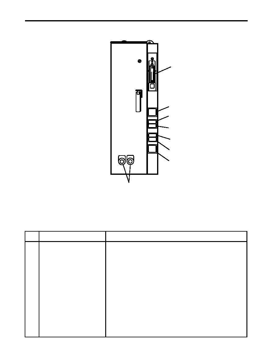
ENGINE ROOM SUPPLY AND EXHAUST FAN MOTOR CONTROLLERS
ON
1
OFF
2
POWER
AVAILABLE
3
SLOW
FAST
4
FAST
5
SLOW
6
STOP
RESET
RESET
7
8
Figure 17. Engine Room Supply and Exhaust Fan Motor Controllers
Table 17. Engine Room Supply and Exhaust Fan Motor Controllers (refer to figure 17)
Key
Control/Indicator
Function
1
ON/OFF Switch
This switch provides ON/OFF control with circuit protection.
2
POWER AVAILABLE Indicator
This indicator illuminates (green) to indicate that power is available to the
controller.
3
SLOW Indicator
This indicator illuminates to indicate that the fan is operating at SLOW speed.
4
FAST Indicator
This indicator illuminates to indicate that the fan is operating at FAST speed.
5
FAST Pushbutton
This pushbutton is used to operate the fan motor at FAST speed.
6
SLOW Pushbutton
This pushbutton is used to operate the fan motor at SLOW speed.
7
STOP Pushbutton
This pushbutton is used to STOP the fan motor.
8
RESET Pushbutton
This pushbutton resets the motor controller.
0043 00-28
|
||
|
||


