
| Tweet |

Custom Search
|
|

|
||
 TM 55-1925-273-10-1
0044 00
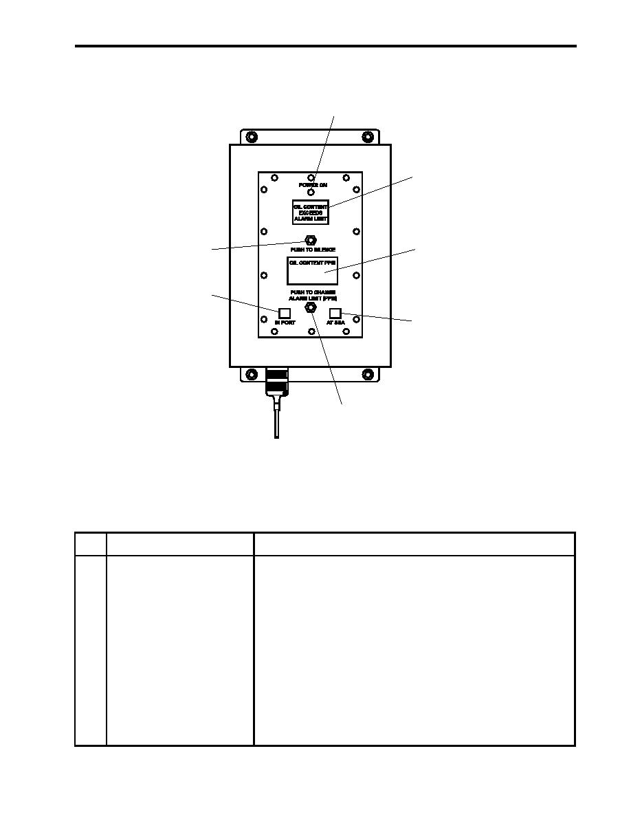
REMOTE INDICATOR (ALARM) ASSEMBLY
1
2
7
3
6
4
5
Figure 19. Remote Indicator (Alarm) Assembly
Table 19. Remote Indicator (Alarm) Assembly (refer to figure 19)
Key
Control/Indicator
Function
1
POWER Indicator
This indicator illuminates to indicate that the OCM is operating.
2
OIL CONTENT EXCEEDS
This indicator illuminates to indicate that the effluent oil content exceeds
ALARM LIMIT Indicator
the selected alarm limit.
3
EFFLUENT OIL CONTENT
This displays the effluent oil content in ppm.
Display
4
70 PPM AT SEA Indicator
This indicator illuminates to indicate that the 70 PPM (at sea) alarm limit is
selected.
5
PUSH TO CHANGE
This switch toggles between the 15 and 70 PPM alarm limit settings when
ALARM LIMIT Switch
the alarm limit selector switch in the sampling/sensor assembly is set to
REMOTE. The sampling/sensor assembly is located in the engine room.
0044 00-31
|
||
|
||


