
| Tweet |

Custom Search
|
|

|
||
 TM 55-1925-273-10-1
0046 00
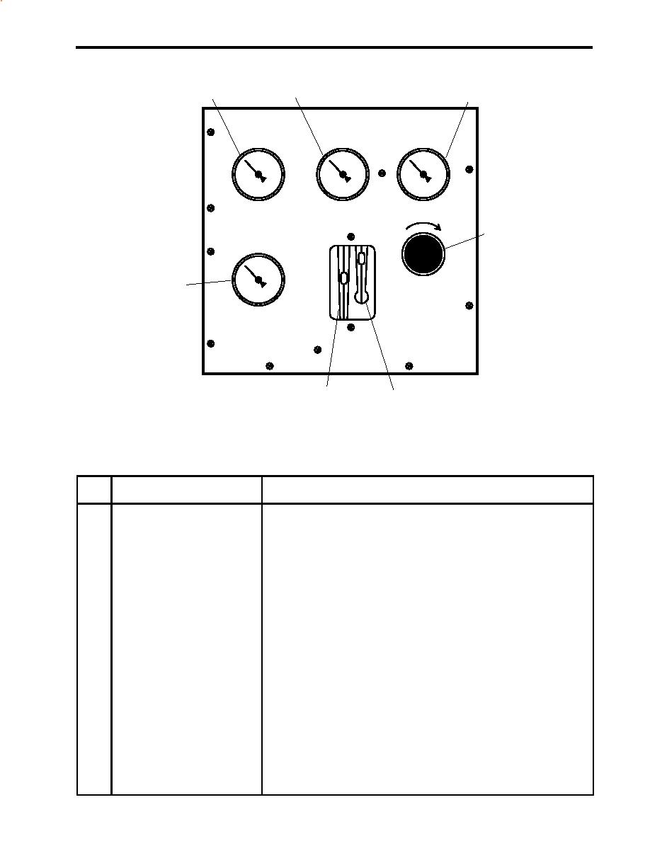
FLOW CONTROL PANEL INDICATORS AND CONTROLS
2
1
3
SYSTEM OPERATION
HIGH PRESSURE
BRINE DISCHARGE
PRESSURE
PUMP INLET
PRESSURE
800-900 PSI
15-50 PSI
0-25 PSI
REASE
INC
PRODUCT WATER
4
OUTPUT PRESSURE
BRINE
PRODUCT
0-25 PSI
7
SYSTEM
HIGH PRESSURE
REGULATOR
6
5
Figure 10. Flow Control Panel Indicators and Controls
Table 10. Flow Control Panel Indicators and Controls (refer to figure 10)
Key
Control/Indicator
Function
1
BRINE DISCHARGE
This gauge indicates the pressure in the brine discharge header.
PRESSURE Gauge
2
HIGH PRESSURE PUMP
This gauge indicates the pressure at the high pressure pump inlet. It is used
INLET-PRESSURE Gauge
in combination with the 5-micron filter inlet pressure gauge to determine
differential pressure across the 5-micron filter.
3
SYSTEM OPERATION
This gauge indicates the output pressure of the high pressure pump.
PRESSURE Gauge
4
SYSTEM HIGH PRESSURE
This valve controls the operating pressure in the ROWPU. Turn the valve
REGULATOR Valve
clockwise to increase system pressure, and turn it counterclockwise to
decrease the system pressure.
5
PRODUCT Flow Meter
This flow meter indicates product water flow in gallons per hour. It also
provides an indication water quality being produced.
6
BRINE Flow Meter
This flow meter indicates the amount of brine that the ROWPU is expelling
overboard.
7
PRODUCT WATER OUTPUT
This gauge indicates the pressure present in the product water line.
PRESSURE Gauge
0046 00-17
|
||
|
||


