
| Tweet |

Custom Search
|
|

|
||
 TM 55-1925-273-10-1
0046 00
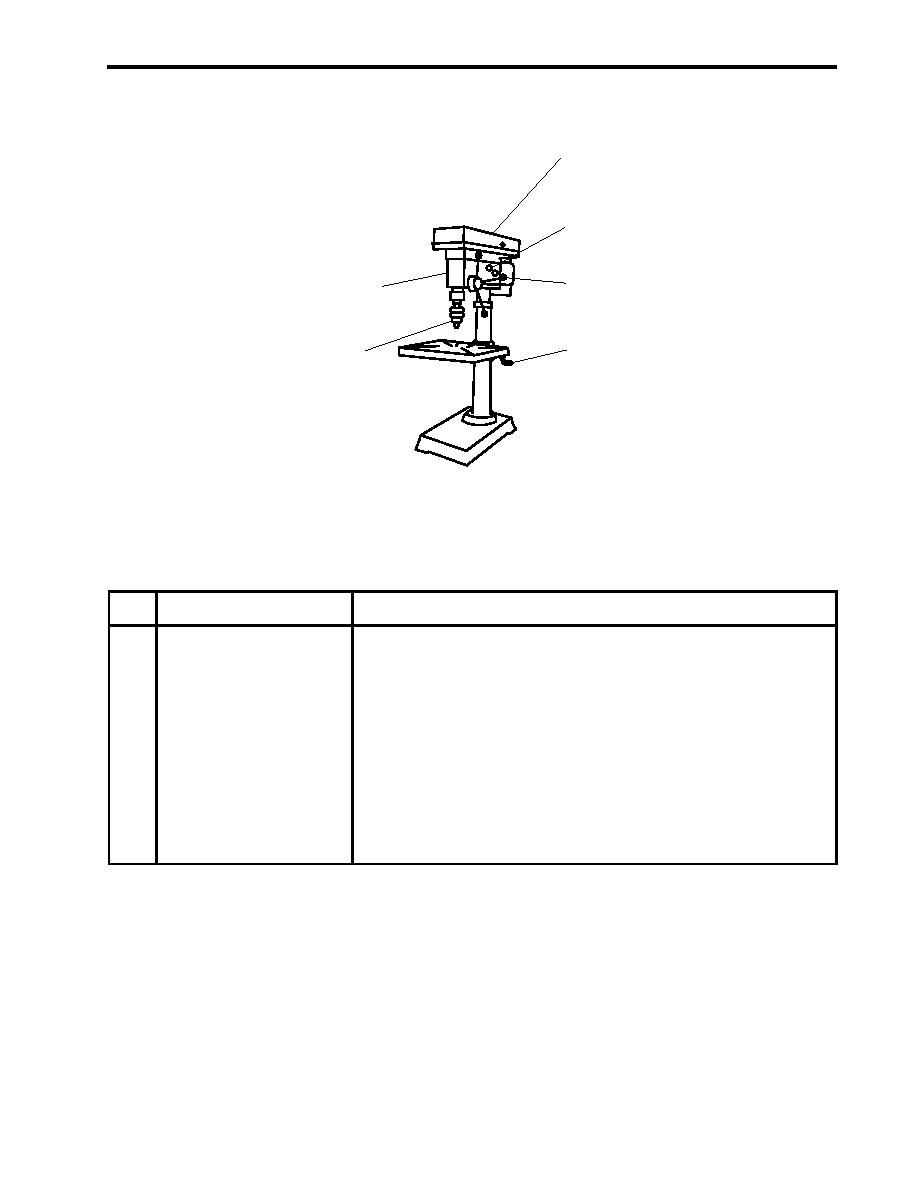
DRILL PRESS
1
2
3
6
4
5
Figure 22. Drill Press
Table 22. Drill Press (refer to figure 22)
Key
Control/Indicator
Function
1
Top Cover
This provides access to the belts and pulleys to change the speed of the drill
press.
2
Cam Handle
This engages and disengages the drive train.
3
Handle
The handle controls the height of the spindle.
4
Table Crank
The crank is used to raise or lower the table.
5
Chuck
The chuck is used to secure drill bits.
6
ON/OFF Switch
This switch turns the drill press ON and OFF.
0046 00-31
|
||
|
||


