
| Tweet |

Custom Search
|
|

|
||
 TM 55-1925-273-10-1
0064 00
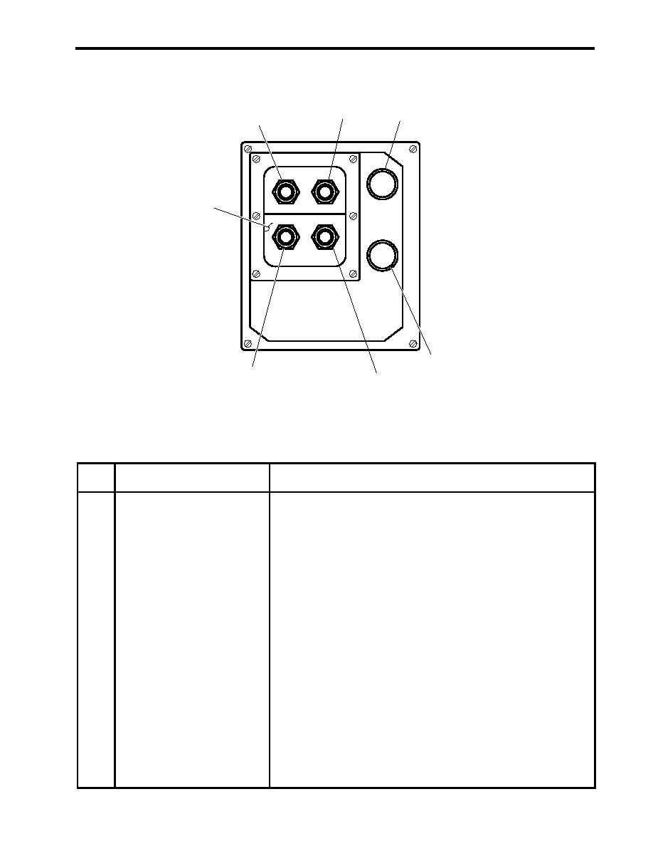
FIRE PUMP START/STOP PANEL
2
3
1
NO.
1
7
NO.
2
FIRE PUMP REMOTE CONTROL
NOTE:
VALVE ALIGNMENT OF STANDBY FIRE
PUMP FOR FIREMAIN SERVICE SHALL BE
MAINTAINED AT ALL TIMES.
4
6
5
Figure 9. Fire Pump START/STOP Panel
Table 9. Fire Pump START/STOP Panel (refer to figure 9)
Key
Control/Indicator
Function
1
Fire and General Service Pump 1
PUSH this button to START fire and general service pump 1 from the
START Pushbutton
pilothouse.
2
Fire and General Service Pump 1
PUSH this button to STOP fire and general service pump 1 from the
STOP Pushbutton
pilothouse.
3
Fire and General Service Pump 1
This lamp illuminates when fire and general service pump 1 is running.
RUN Indicator
4
Fire and General Service Pump 2
This lamp illuminates when fire and general service pump 2 is running.
RUN Indicator
5
Fire and General Service Pump 2
PUSH this button to STOP fire and general service pump 2 from the
STOP Pushbutton
pilothouse.
6
Fire and General Service Pump 2
PUSH this button to START fire and general service pump 2 from the
START Pushbutton
pilothouse.
7
ALIGNED FOR GENERAL
This plate slides over the START and STOP pushbuttons for the fire and
SERVICES Blockout Plate
general service pump that is aligned for to provide general service water for
the vessel. The exposed START and STOP pushbuttons are for the fire and
general service pump aligned for firemain service.
0064 00-13
|
||
|
||


