
| Tweet |

Custom Search
|
|

|
||
 TM 55-1925-273-10-1
0069 00
8
2
1
1
8
3
2
6
4
5
7
7
5
3
4
6
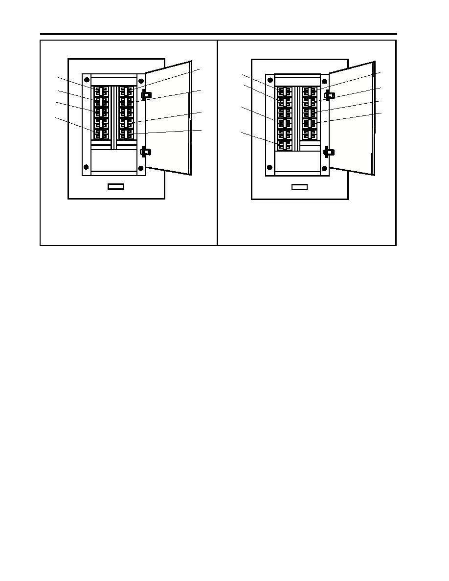
Figure 2. 120V Exterior Emergency Lighting
Figure 1. 120V Main Deck, 01 & 02 Emergency
Panel No. 2
Lighting Panel No. 1
NOTE
Ensure that the battery chargers are turned ON.
c.
In the engine room, starboard side, at 120V emergency distribution panel No. 1, set the following circuit breakers
to ON:
(1)
ENGINE ROOM EMERGENCY LIGHTS. (PORT). (figure 3, item 1)
(2)
ENGINE ROOM EMERGENCY LIGHTS. (STBD). (figure 3, item 2)
(3)
AMS No. 2. EMERGENCY LIGHTS. (figure 3, item 3)
(4)
MACHINERY DC CONTROL BATTERY CHARGER. (figure 3, item 4)
(5)
MONITOR SYSTEM CIRCUIT. (figure 3, item 5)
(6)
SSDG No. 1. BATTERY CHARGER. (figure 3, item 6)
(7)
REMOTE PROPULSION INDICATOR PANEL. (figure 3, item 7)
(8)
STEERING GEAR ROOM & TOWING GEAR LIGHT. (figure 3, item 8)
(9)
BOW THRUSTER & AMS No. 1. EMERGENCY LIGHTS. (figure 3, item 9)
NOTE
If necessary to silence the fire alarm, obtain the key, unlock the fire and smoke detection panel,
and press the ALARM SILENCE pushbutton.
(10) FIRE DETECTION SYSTEM. (figure 3, item 10)
0069 00-2
|
||
|
||


