
| Tweet |

Custom Search
|
|

|
||
 TM 55-1925-273-10-1
0069 00
f.
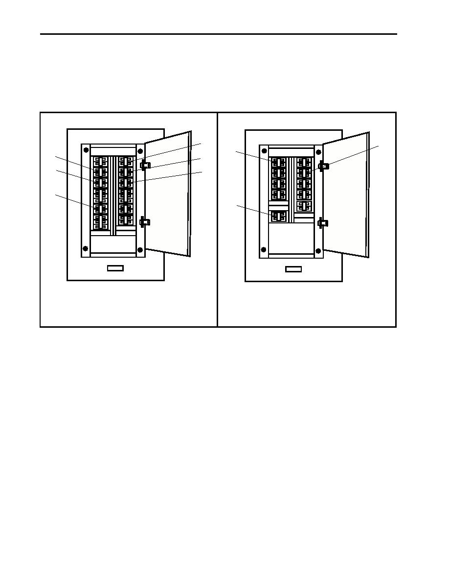
In the galley, at 120V distribution panel No. 1, set the following circuit breakers to ON:
(1)
GALLEY RECEPTACLES. (figure 6, item 1)
(2)
GALLEY LIGHTS. (figure 6, item 2)
(3)
GAYLORD CONT CABINET. (figure 6, item 3)
1
2
1
6
2
5
3
4
3
Figure 5. 120V Distribution Panel No. 3
Figure 6. 120V Distribution Panel No. 1
g.
In the engine room, at 120V distribution panel No. 4, set the following circuit breakers to ON:
(1)
ENGINE ROOM LIGHTS. (figure 7, item 1)
(2)
BOWTHRUSTER COMPT & AUXILIARY MACHINERY SPACES 1 & 2 LIGHTS. (figure 7, item 2)
(3)
HOLD LEVEL & FAN TAIL RECEPTACLES. (figure 7, item 3).
(4)
SHIPS SERVICE DIESEL GENERATOR JACKET WATER HEATER No .2. (figure 7, item 4)
(5)
BOW THRUSTER ENGINE JACKET WATER HEATER. (figure 7, item 5)
(6)
PUMP DRIVE ENGINE JACKET WATER HEATER. (figure 7, item 6)
(7)
SHIPS SERVICE DIESEL GENERATOR JACKET WATER HEATER No. 1. (figure 7, item 7)
h.
In the engine room, at 440V power panel No. 1, set the following circuit breakers to ON:
(1)
MAIN ENGINE JACKET WATER No. 1./TURBO OIL PUMP No. 1/WATER LAY OVER PUMP No. 1.
(figure 8, item 1)
(2)
MAIN ENGINE JACKET WATER No. 2./TURBO OIL PUMP No. 2/WATER LAY OVER PUMP No. 2.
(figure 8, item 2)
0069 00-4
|
||
|
||


