
| Tweet |

Custom Search
|
|

|
||
 TM 55-1925-273-10-1
0069 00
2
1
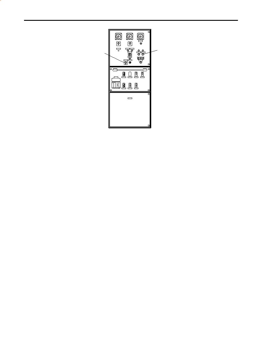
Figure 14. Emergency Switchboard
NOTE
Opening the shore power circuit breaker and closing the generator circuit breaker are done very
quickly.
d.
At the main switchboard in the EOS:
(1)
Set the SHORE POWER CIRCUIT BREAKER (figure 13, item 7) to the OFF position.
(2)
Set the following circuit breakers to the ON position:
(a) GEN #1 CKT. BKR. (figure 13, item 8)
(b) 3-25 KVA 1 XFMRS (figure 13, item 9)
(c) ENG. RM. SUPPLY FAN #1 (figure 13, item 10)
(d) ENGINE ROOM POWER PANEL NO.1 (figure 13, item 11)
(e) ENG. RM. EXH. FAN #1 (figure 13, item 12)
(f)
BUS TIE CIRCUIT BREAKER. (figure 13, item 13)
(g) ENG. RM. EXH. FAN #2 (figure 13, item 14)
(h) ENG. ROOM. SUPPLY FAN #2 (figure 13, item 15)
e.
On the aft bulkhead of the EOS, at the load center distribution panel, set the following circuit breakers to ON:
(1)
120V DISTRIBUTION PANEL No. 2. (01 LEVEL). (figure 15, item 1)
(2)
120V DISTRIBUTION PANEL No. 3. (MAIN DECK) (figure 15, item 2)
0069 00-10
|
||
|
||


