
| Tweet |

Custom Search
|
|

|
||
 TM 55-1925-273-10-1
0070 00
1
4
3
2
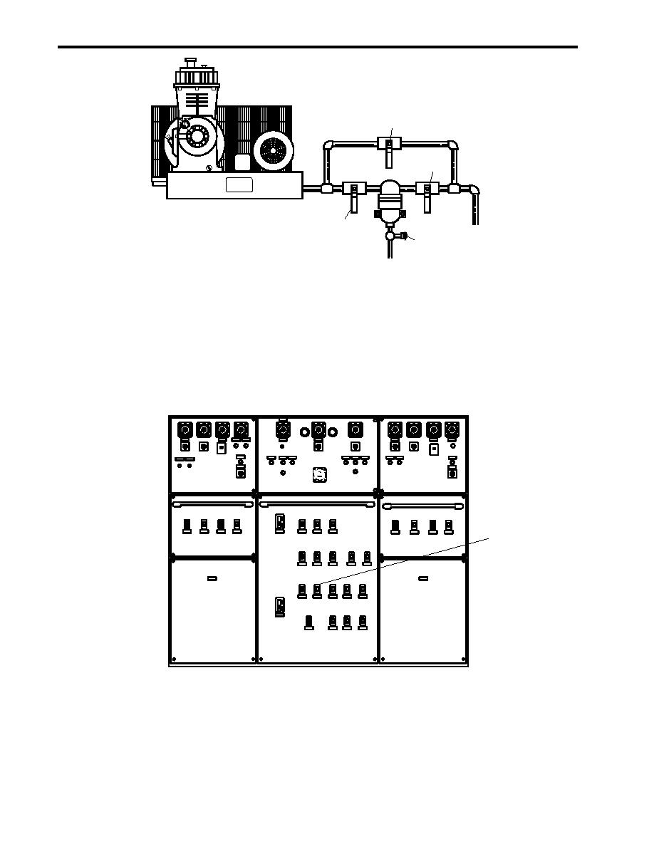
Figure 2. Dryer Valve Locations
6.
Ensure that valves CA-46 and CA-47, STG AIR TK DR (figure 1, items 8 and 9) are CLOSED.
7.
Ensure that valves CA-98 and CA-99 (figure 1, item 10) are OPEN.
8.
At the main switchboard, set the AUX MACH SPACE NO. 1 PWR PANEL NO. 4 circuit breaker (figure 3, item 1) to ON.
1
Figure 3. EOS Main Switchboard
9.
At 440V power panel No. 4 (figure 4), set the following circuit breakers to ON:
a. AIR COMPRESSOR No. 1. (figure 4, item 1)
b. AIR COMPRESSOR No. 2. (figure 4, item 2)
0070 00-2
|
||
|
||


