
| Tweet |

Custom Search
|
|

|
||
 TM 55-1925-273-10-1
0072 00
1
START
2
STOP
RESET
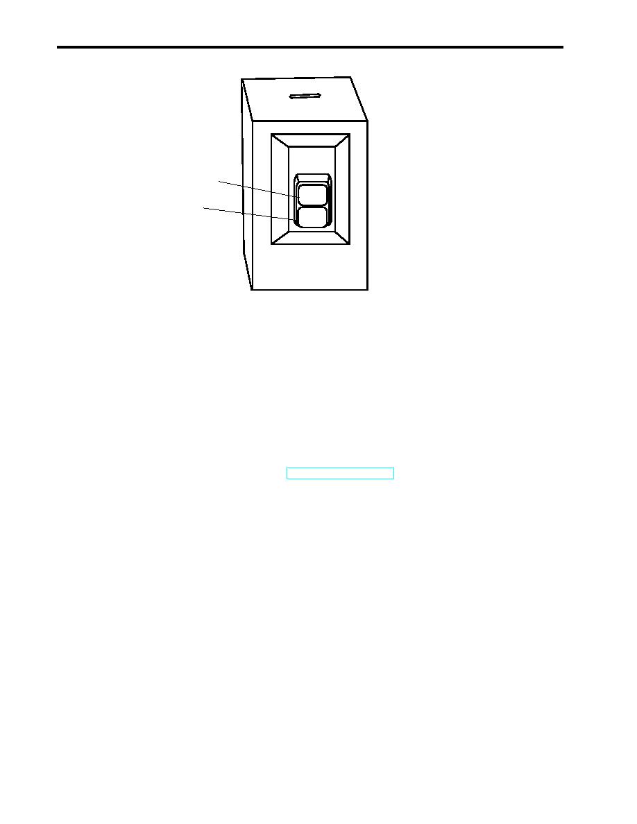
Figure 14. Port Main Engine Prelube Pump Motor Controller
6.
OPEN valve LO-47, C.O.V. PRELUBE PMP. DISCH. (figure 13, item 3).
7.
At the prelube pump motor controller (figure 13, item 4), PUSH the START pushbutton (figure 14, item 1).
8.
At 120V emergency distribution panel No. 1, ensure that the following circuit breakers are set to ON:
NOTE
If necessary to silence the fire alarm, obtain the key, unlock the fire and smoke alarm panel and
press the ALARM SILENCE pushbutton (TM 55-1925-292-14&P).
a.
FIRE DETECTION SYSTEM. (figure 5, item 1).
b.
E.O.T. SYSTEM. (figure 5, item 2).
c.
MONITOR SYSTEM CIRCUIT. (figure 5, item 3).
d.
REMOTE PROPULSION INDICATOR PANEL. (figure 5, item 4).
9.
OPEN the following fuel system valves:
a.
FO-19, F.O. SPLY TO PORT ME No. 2 (figure 6, item 11).
b.
FO-14, F.O. SERV CRSVR (figure 6, item 2).
c.
FO-13, F.O. SERV. SUCT. PORT (remote operator in the main deck fan room) (figure 6, item 12).
d.
FO-33, F.O. RTN TO DAY TK. PORT (figure 6, item 13).
e.
FO-34, F.O. RTN CRSVR (figure 6, item 5).
f.
Four Racor fuel supply cutoff valves (figure 7, item 1) and four Racor fuel discharge cutoff valves (figure 7, item 2)
located at the forward inboard corner of the engine.
0072 00-12
|
||
|
||


