
| Tweet |

Custom Search
|
|

|
||
 TM 55-1925-273-10-1
0074 00
(3)
Start the pump(s) by pressing the START pushbutton(s) (figure 10, item 3).
(4)
Verify that the MOTOR RUN indicator(s) (figure 10, item 4) energize(s).
b.
At the fuel oil station, observe that the TLIs (figure 7, items 1 and 2) indicate that the selected day tank level is
increasing, and the selected supply tank is decreasing.
c.
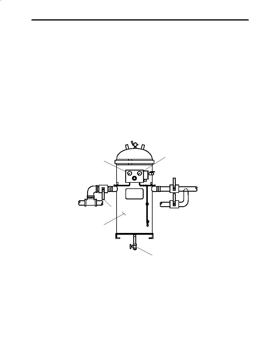
Observe the readings on the inlet pressure gauge (figure 11, item 1) and the discharge pressure gauge (figure 11,
item 2) on the fuel filter/water separator (figure 11, item 3). If the differential pressure between these gauges
exceeds 10 PSI (0.7 bar) or 10 in. Hg (254 mm Hg), secure from fuel transfer and change the filters (TM 55-1925-
283-12&P).
d.
To drain water from the fuel filter/water separator (figure 11, item 3), secure from fuel transfer, CLOSE valve FO-
16, F.O. FLTR/WATER SEP INLET. COV (figure 11, item 4), and OPEN the drain valve (figure 11, item 5)
(located under the deck plate). After draining the water, CLOSE the drain valve, OPEN FO-16, F.O. FLTR/
WATER SEP INLET. COV, and resume fuel transfer.
e.
When the TLIs (figure 7, items 1 and 2) for the selected day tank indicate the desired level, STOP the fuel oil
transfer pump(s), and secure the fuel oil transfer piping system.
2
1
4
3
5
Figure 11. Fuel Filter/Water Separator
4.
Secure the fuel oil transfer piping system:
a.
At the fuel oil transfer pump motor controller(s) 1 and/or 2 (figure 10):
(1)
Press the STOP pushbutton(s) (figure 10, item 5).
(2)
Verify that the MOTOR RUN indicator(s) (figure 10, item 4) go(es) out.
0074 00-9
|
||
|
||


