
| Tweet |

Custom Search
|
|

|
||
 TM 55-1925-273-10-1
0082 00
7
6
1
2
5
3
4
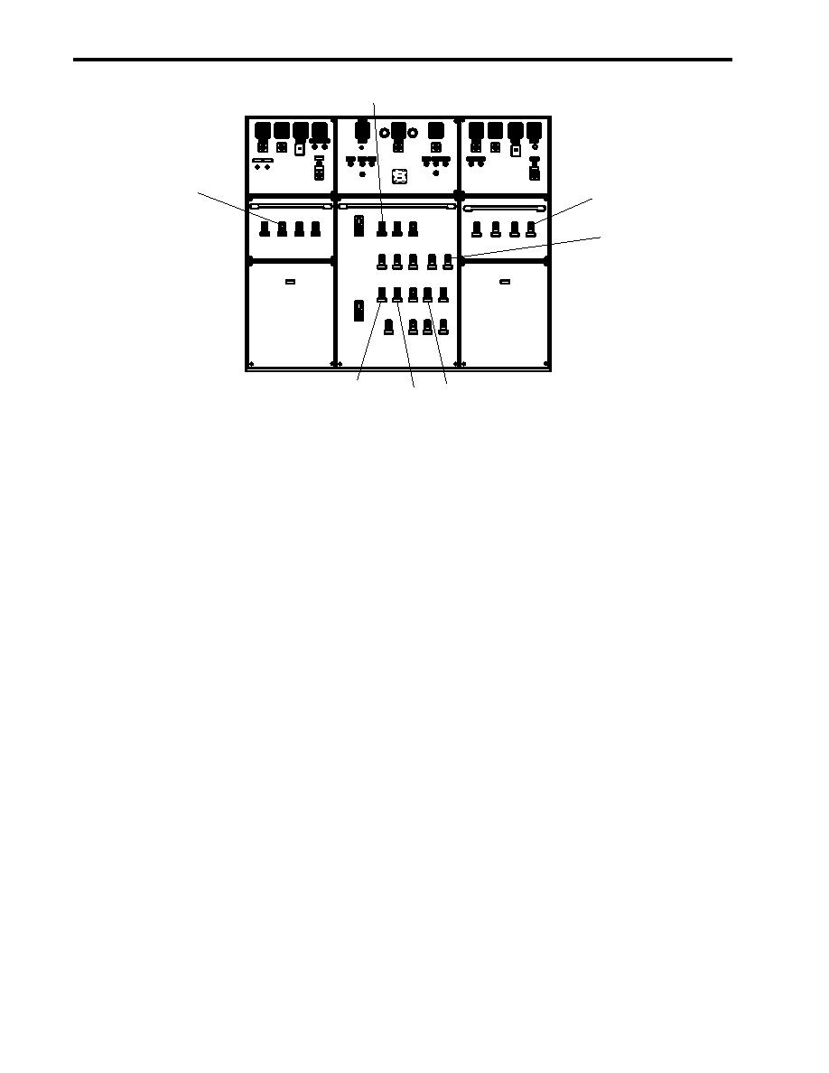
Figure 1. Main Switchboard
2.
At 120V distribution panel No. 4, set the following circuit breakers to ON:
a.
ENGINEERS OPERATING STATION R2-40-1. (figure 2, item 1)
b.
WORKSHOP EXHAUST FAN E02-16-1. (figure 2, item 2)
c.
J.B. FOR SS REFG Nos. 1 & 2 (INC. FAN COIL AND CONTROLERS). (figure 2, item 3)
d.
J.B. FOR A/C REEF SYSTEMS Nos. 1 & 2 (INC. LIQUID LINE SOLENOID VALVES). (figure 2, item 4)
e.
SHIPS SERVICE DIESEL GENERATOR SPACE HEATER No. 2. (figure 2, item 5)
f.
SHIPS SERVICE DIESEL GENERATOR SPACE HEATER No. 1. (figure 2, item 6)
3.
At 440v power panel 1, set the ENGINE. ROOM UNIT HEATER. (figure 3, item 1) circuit breaker to ON.
4.
At 440V power panel No. 5, set the following circuit breakers to ON:
a.
AIR CONDITIONING REFRIGERATION PLANT No. 2. (figure 4, item 1)
b.
STORE REFRIGIRATION PLANT No. 2. (figure 4, item 2)
c.
TOWING GEAR LOCKER UNIT HEATER. (figure 4, item 3)
d.
STORE REFRIGIRATION PLANT No. 1./FREEZE BOX DEFROST HEATER. (figure 4, item 4)
e.
AIR CONDITIONING REFRIGERATION PLANT No. 1. (figure 4, item 5)
f.
UNIT HEATER. (AUXILIARY MACHINERY SPACE No. 2.). (figure 4, item 6)
0082 00-2
|
||
|
||


