
| Tweet |

Custom Search
|
|

|
||
 TM 55-1925-273-10-1
0083 00
6.
Disconnect the plug (figure 2, item 3) from the telephone jack.
7.
Replace the jack cover on the telephone box.
8.
Roll up the phone cord (figure 2, item 2), loop it over the mouthpiece, and place it on the support bracket.
9.
Disconnect one end of the strap from the chest plate, remove it from around the neck, wrap it around the support
bracket, and reconnect it to the chest plate to secure the headset and cord.
10. Replace the headset in its storage box and secure the storage box cover.
INTERCOM SYSTEM
1.
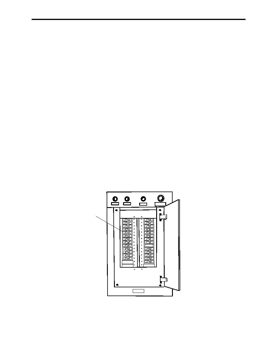
In the Emergency Diesel Generator (EDG) room, at the 120V emergency load center distribution panel, verify that the
PILOTHOUSE EMERGENCY DISTRIBUTION PANEL. circuit breaker (figure 3, item 1) is set to ON.
2.
At the 120V pilothouse emergency distribution panel, set the INTERCOM SYSTEM. circuit breaker (figure 4, item 1)
to ON.
3.
To answer a call:
a.
Turn DOWN and hold the intercom control lever (figure 5, item 1) in the PRESS TO TALK position.
b.
Speak directly into the wire mesh speaker (figure 5, item 2).
c.
Acknowledge the incoming call by giving your station name, then release the intercom control lever (figure 5, item 1).
d.
Each time you answer a call or pass information, you must turn down and hold the intercom control lever (figure 5,
item 1) in the PRESS TO TALK position.
GROUNDDETECTION
PHASEA
PHASE B
PHASE C
PUSHTOLIGHT
LAMPS
1
Figure 3. 120V Emergency Load Center Distribution Panel
0083 00-3
|
||
|
||


