
| Tweet |

Custom Search
|
|

|
||
 TM 55-1925-273-10-1
0084 00
GENERAL ALARM SYSTEM OPERATION
1.
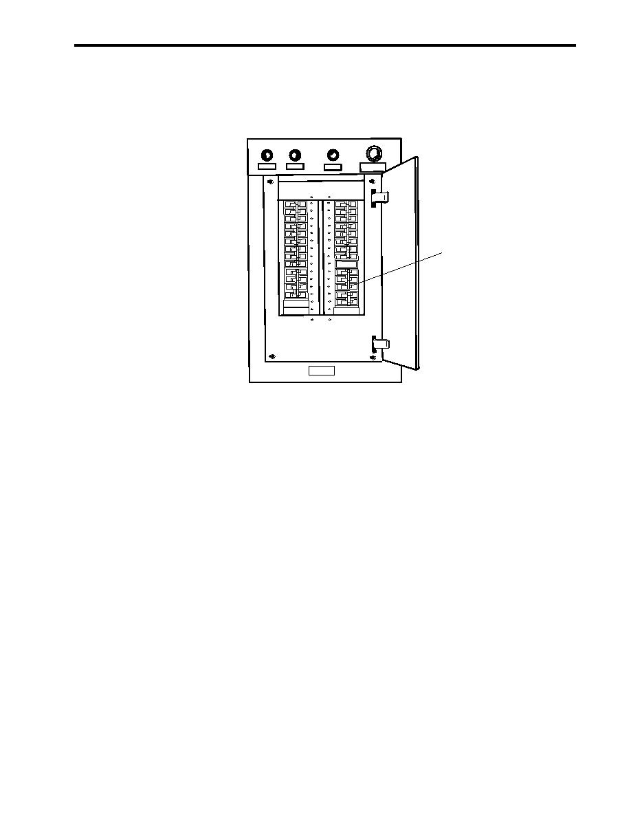
In the Emergency Diesel Generator (EDG) room, at the 120V emergency load center distribution panel, set to ON the
GENERAL ALARM BATTERY CHARGER. circuit breaker (figure 3, item 1).
GROUNDDETECTION
PHASEA
PHASE B
PHASE C
PUSHTOLIGHT
LAMPS
1
Figure 3. 120V Emergency Load Center Distribution Panel
NOTE
The general alarm system is a 24 VDC system, and it is always powered by the general alarm
battery charger or battery bank.
2.
Test the general alarm system by activating the contact makers in the pilothouse and the 01 Level passageway.
3.
Verify operation of the general alarm system by ensuring that the bells provide an audible alarm throughout the Large
Tug (LT) and the rotating lights operate when each actuator is pressed.
DOOR ALARM AND FREEZER ALARM SYSTEMS OPERATION
1.
At 120V main deck, 01 & 02 emergency lighting panel No. 1, set the following circuit breakers to ON:
a.
FREEZER ALARM. (figure 4, item 1)
b.
ALARM SWITCHBOARD (HIGH TEMPERATURE & SPRINKLER). (figure 4, item 2)
2.
Verify operation of the radio room door alarm system by opening the radio room door and verifying that the alarm
buzzer and indicator on the alarm switchboard in the pilothouse activates.
3.
Verify operation of the arms stowage alarm system by opening the arms stowage room door and verifying that the alarm
buzzer and indicator on the alarm switchboard in the pilothouse activates.
0084 00-3
|
||
|
||


