
| Tweet |

Custom Search
|
|
|
|||||

|
|||||
 TM 55-1925-273-10-1
0089 00
7
6
8
9
AMS 1
3
EOS
4
ENGINE
ROOM
PUMP DRIVE
DETAIL A
ENGINE
2
5
1
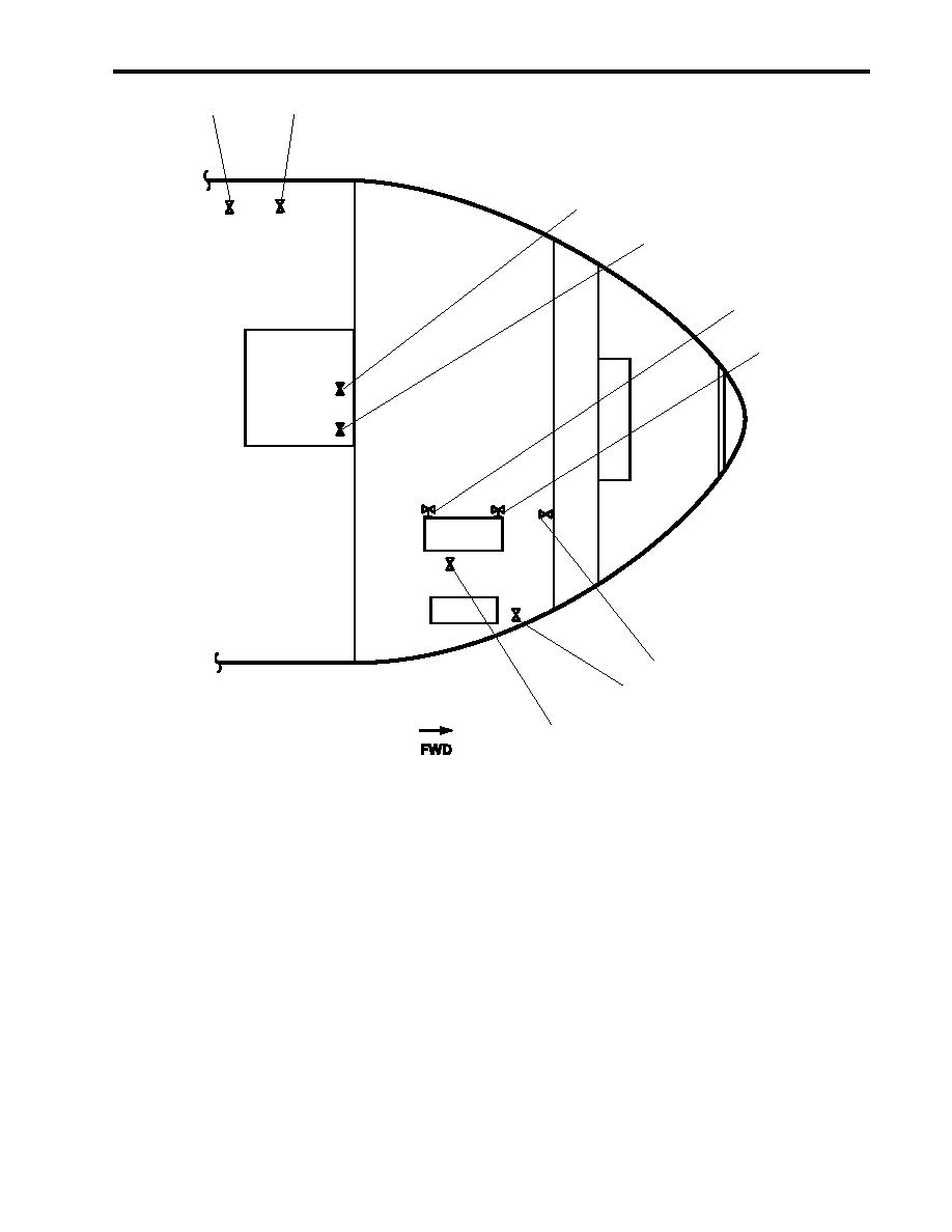
Figure 2. Towing Machine Hydraulic System Valve Locations
4.
At 120V distribution panel No. 4, set the PUMP DRIVE ENGINE JACKET WATER. circuit breaker (figure 3, item 1)
to ON.
5.
Start the pump drive engine by performing the following steps:
a.
Place the firefighting pump power take-off control lever (figure 4, item 1) in the disengaged (aft) position.
b.
Move the governor control lever (figure 5, item 1) to the half engine speed position (approximately straight up).
c.
In AMS 1, check that the PMP DR ENG STG AIR PRESS air supply pressure gauge indicates an air start reading
between 100 to 120 PSI (6.9 to 8.3 bar) in order to operate properly.
d.
On the pump drive engine control panel, turn the START/STOP pushbutton (figure 5, item 2) clockwise to release
the pushbutton to the OUT position.
0089 00-3
|
|||||
|
|||||


