
| Tweet |

Custom Search
|
|

|
||
 TM 55-1925-273-10-1
0107 00
8.
In AMS 1, at the AMS 1 supply fan motor controller.
a.
Press and release the STOP pushbutton (figure 11, item 1).
b.
Verify that the FAST speed indicator (figure 11, item 2) or SLOW speed indicator (figure 11, item 3) goes out.
c.
Set the ON-OFF switch (figure 11, item 4) to the OFF position.
d.
Verify that the POWER AVAILABLE indicator (figure 11, item 5) goes out.
9.
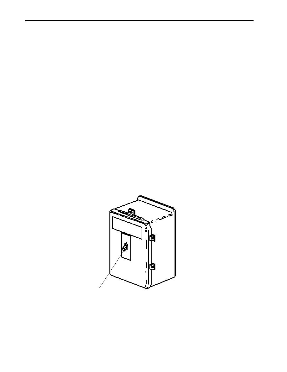
In AMS 2, at the workshop exhaust fan motor controller, perform the following actions:
a.
Place the ON-OFF switch (figure 12, item 1) in the OFF position.
10. At the sanitary spaces exhaust fan motor controller perform the following:
a.
Press and release the STOP pushbutton (figure 10, item 1).
b.
Verify that the MOTOR RUN indicator (figure 10, item 2) goes out.
c.
Set ON-OFF switch (figure 10, item 3) to OFF.
d.
Verify that the POWER AVAILABLE indicator (figure 10, item 4) goes out.
ON
OF
F
1
Figure 12. Workshop Exhaust Fan Motor Controller
0107 00-10
|
||
|
||


