| Tweet |

Custom Search
|
|

|
||
 0145 00
TM 11-5895-1847-12&P
a.
Loosen screw (10) and insert PLGRSB-PWR/DC POWER cable negative wire (11) in junction box terminal
block (9). Tighten screw (10).
b.
Loosen screw (12) and insert PLGRSB-PWR/DC POWER cable positive wire (13) in junction box terminal
block (9). Tighten screw (12).
c.
Install PLGRSB-PWR/DC POWER cable ground wire (16) to ground stud and secure with washer (15) and
nut (14).
d.
Tighten screws (17) on junction box cable clamp (18) to secure GMDSS PLGR communications power
cable (8).
2.
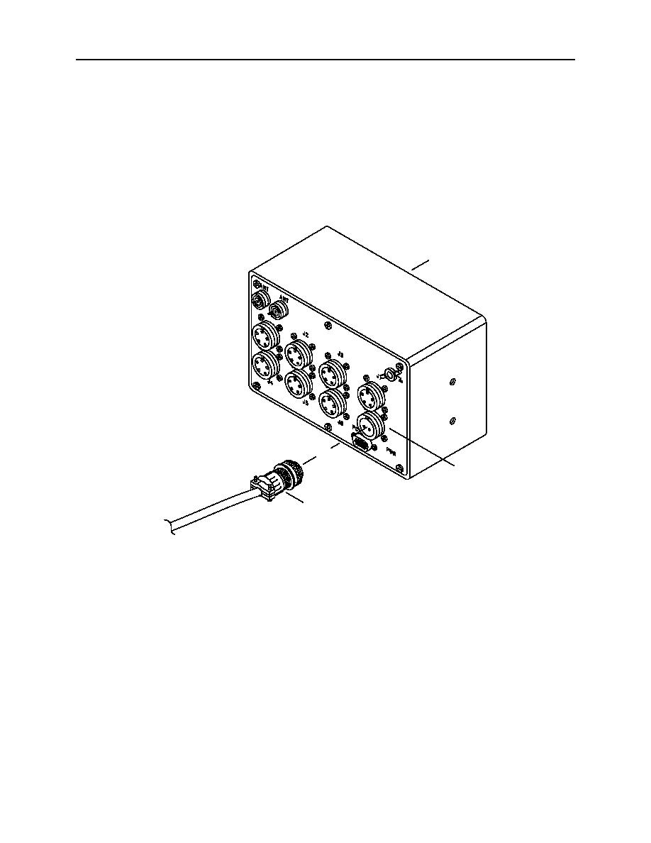
Plug the power cable plug (1) into the port (2) of the AN/PSN-11 interface and switchbox (3) back.
3
2
1
2C141-6
3.
Tighten the connector shell of the power cable plug (1), tagged GMDSS POWER, on the back of the AN/PSN-11
interface and switchbox.
4.
Install nylon cable ties that secures GMDSS PLGR communications power cable to other cables.
5.
Turn power on at the GMDSS DC converter. Place the switch in the ON position.
6.
Turn power on at the GMDSS power supply. Place the switch in the ON position.
END OF WORK PACKAGE
0145 00 6
|
||
 |
||