| Tweet |

Custom Search
|
|
|
|
||

|
||
 TM 55-1905-217-12
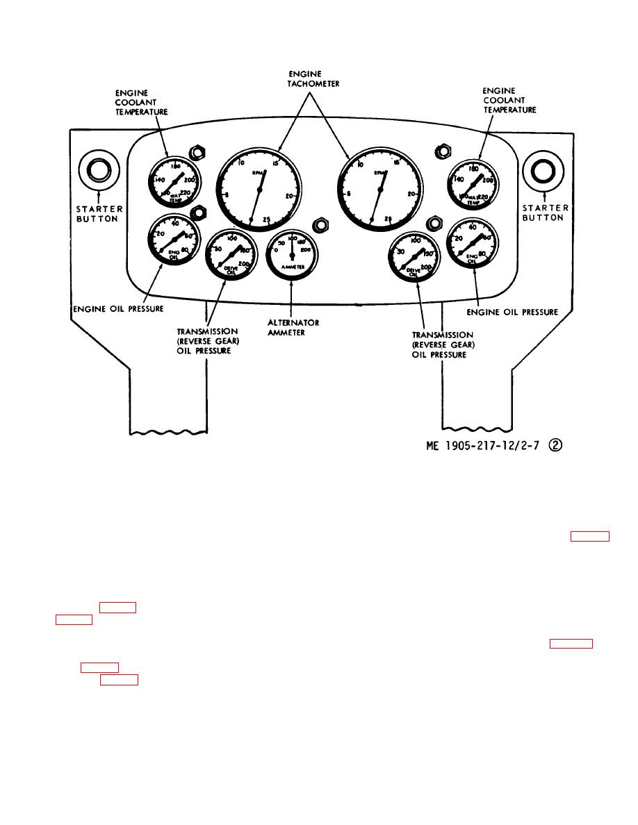
Figure 2-7.2. Engine room controls and indicators, hull numbers 8540 thru 8560 and 8580 thru 8618. (Sheet 2 of 2)
gines is mounted on the panel. The gages indicate the
bers 8540 thru 8560 and 8'580 thru 8618. When a ramp
temperature of the coolant being circulated through the
hoist pump is operating, the gage indicates the pressure
engine.
in the system.
(5) Transmission oil pressure gage. The
(9) Steering hydraulic pressure gage (16, fig. 2-1)
Furnished on hull numbers 8500 thru 8519. This gage
control panel contains a separate gage for each of the
two propulsion units.
indicates the pressure available in the steering hydraulic
(6) Engine oil pressure gages. There are four
system to operate the rudders.
(10) Rudder angle indicator. The indicator will
oil pressure gages, one for each of the four engines.
(7) Starting system hydraulic pressure gage.
show the position of the rudders. It is connected to a
The gage (18, fig. 2-1) hull numbers 8500 thru 8519 and
sender located in the lazarette at the port side rudder
(20, fig. 2-5) hull numbers 8540 thru 8560 and 8580 thru
post
(11) Sight glass, steering system 8 gallon
8618, only on hull numbers listed, indicate the pressure
expansion tank, hull numbers 8500 thru 8519 (fig. 2-27).
available for starting inboard engines.
(8) Ramp hoist hydraulic System pressure
Tank is mounted aft in the pilot house. Oil level in the
gage (17, fig. 2-1). Furnished on hull numbers 8500 thru
tank should ,be within one inch of the red center line of
8619 and (18, fig. 2-5) on hull num-
the sight glass.
2-11
|
||
 |
||