| Tweet |

Custom Search
|
|

|
||
 TM 55-1905-217-
3-13. Storage Batteries, Cables, and Terminals (fig.
a. Inspection. Inspect batteries for leaks, corrosion,
proper electrolyte level, and breaks or cracks. Inspect
cables and terminals for corrosion and for broken cables
or terminals.
b Servicing and Testing.
(1) Clean batteries and terminals with a solution
of water and baking soda and wipe dry.
Keep batteries filled to proper level with electrolyte.
(2) Test the specific gravity of each cell with a
hydrometer. If the specific gravity reading is below 1.225
on the hydrometer, charge the battery. Specific gravity
readings of 1.260-to1.270 on the hydrometer indicate a
fully charged battery.
c. Removal.
(1) Disconnect and remove the negative lead,
then disconnect and remove the positive lead at the
battery.
(2) Remove battery.
d. Installation. Reverse procedure in c above, using
a fully-charged battery.
3-14. Hydraulic Steering System Filter
Observe the filter condition indicator (fig. 230) daily. The
filter element must be changed when the needle moves
into the red danger zone. If filter requires changing,
report to higher authority.
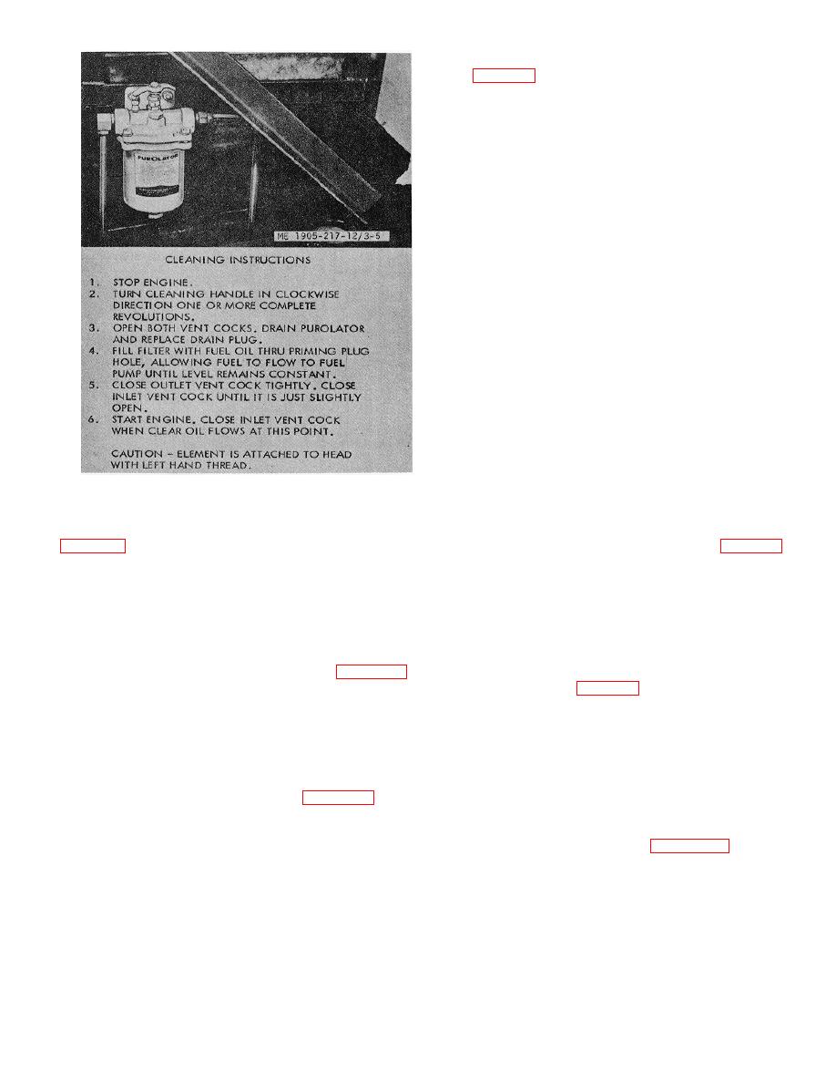
Figure 3-5. Primary fuel line strainers, hull numbers 8500
3-15. Ramp Hoist Hydraulic System Filter
thru 8519
Observe the filter condition indicator (fig. 2-29) daily
Crankcase breather screens are mounted between the
when system is in operation. The filter elements must be
engine blocks, and should be serviced every 8 hours.
changed when the needle moves into the red damage
zone. If servicing of filter ,is indicated, report to
organizational maintenance.
3-11. Alternators and Belt Adjustments
3-16. Ramp Hoist Hydraulic 'System Strainer (Hull
There are two alternators, one mounted on the inboard
Numbers 8500 thru 8519)
engine of each propulsion unit. The alternators are belt
driven from the crankshaft pulley. Refer to figure 3-8 for
alternator belt adjustment.
Check indicator (fig. 2-8.1) when ramp hoist ,system is in
operation. If servicing of strainer is indicated, report to
3-12. Fuses
organizational maintenance.
3-17. Bilge Pumps
Fuses are located in the distribution paned. The fuses are
15-amp, type AGU. Refer to figure 39 for fuse replacement.
In hull numbers 8540 thru 8560 and 8580 thru 8618 the
The landing craft is equipped with three bilge pump. Two
fuses are 10amp, type AGU. Refer to figure 2-5 for fuse
pumps ate mounted on the inboard engine of the port
location.
propulsion unit and one pump is mounted on the inboard
engine of the starboard propulsion unit. Adjust the bilge
pump belts as instructed in figure 3-11. Hull numbers
3-11
|
||
 |
||