| Tweet |

Custom Search
|
|

|
||
 TM 55-1905-217-12
If quick warm-up is attempted by burning the propeller,
the ship must be securely tied to the clock with no loose
lines or floating obstructions to foul the propeller.
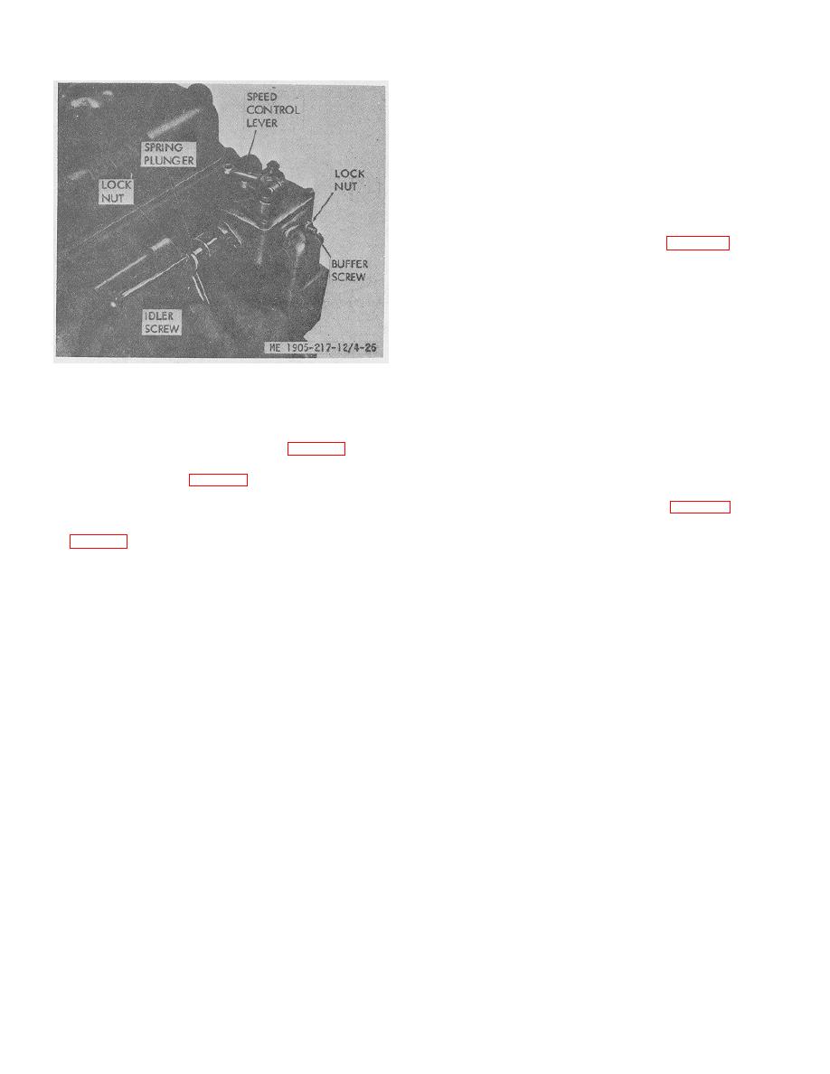
(5) Set governor no-load top speed. Usually the
top no-load speed is set the same on both governors of
twin units before the engines leave the factory. If check
as outlined below shows top no-load speeds to be
different on the two governors, correct as follows:
(a) With both engines warmed up, stop engines and
disconnect throttle control rod (11, fig. 4-27) for "B"
engine by removing pin at clevis (14).
(b) Start "D" engine, declutch and move master
throttle to "FULL" open position.
(c) Note and record maximum no-load speed as
indicated by tachometer.
Figure 4-26. Adjusting engine idle speed.
(d) Stop engine and connect throttle control tube for
"B" engine and disconnect "D" engine.
b The throttle linkage may be adjusted after
(1) With engines stopped, set the throttle setting the
(e) Start "B" engine, declutch, and with master
valves, timing the injectors, adjusting the governor and
throttle in "FULL" open position, note and record speed.
the injector operating linkage as follows (fig. 4-27).
(f) If no-load speeds of the two engines are not the
control cross shaft (15, fig. 4-27) so that throttle control
same, increase the speed of low engine by adding shims
levers (17) are in a vertical position as shown at "A-A".
(5) between the high speed spring (4, fig. 4-27) and the
spring plunger (3). To add shims, remove low-speed
(2) With engines stopped, adjust turnbuckles
adjusting screw cover (1), back out nut (2), and place
(13 fig. 4-27) on the two throttle control rods so that pins
shims -between inner end of spring and shoulder on
in the throttle control levers at governor cover rest
plunger. Add one shim at a time and check speed after
against the shoulders of the control cams (8) in the
each shim is added.
"IDLE" position at the two governors.
(6) Synchronize engine speeds at no-load.
(3) Now move master throttle (16) to "FULL"
Speeds of the two engines must be synchonized to
open position, at which setting the pin in throttle lever
obtain, as nearly as possible, the same no-load speeds in
(24) at both governors should just strike the extreme end
the range just below the rated load speed by 'adjusting
of the slot in the cam (8) at the "RUN" position. If either
the linkage to each governor. Thus, a unit rated at 1,850
or both pins do not reach end of slot in cams, adjust
rpm should have the engines synchronized at 1,700-
turnbuckles (13) to bring about this condition. The linkage
1,800 rpm. Synchronize as follows:
must be so adjusted that the pins in the throttle ,levers at
governor covers reach "RUN" position in the control cam
(a) with engines warmed up, declutch both engines
at exactly the same time. Do not put any strain in the
and move master throttle to such ,position that speed of
throttle linkage when making this adjustment.
"B" engine is 1,750 rpm as -recorded by the tachometer.
Lock the master throttle in this position.
(4) Start and warm up both engines to
operating temperature. Move master throttle to "IDLE"
(b) Note speed of the "D" engine. If the speeds of
position. Declutch both engines and set idling speed of
the two engines are not the same, loosen the two
each engine to 500 rpm.
locknuts at turnbuckle on the '"D" engine, and by
adjusting turnbuckle, shorten throttle rod to increase or
NOTE
lengthen to decrease engine speed.
Engine may be brought up to operating
temperature by declutching engines and setting throttle to
(c) Unlock and move master throttle to "FULL" open
approximately 1,200 engine Wpm.
position. In the "FULL" open position, without strain on
the throttle linkage, the
4-29
|
||
 |
||