| Tweet |

Custom Search
|
|

|
||
 TM 55-1905-217-12
low when testing the alternator system.
(4) The voltage regulator used on hull
numbers 8540 thru 8560 and 8580 thru 8618 can be
adjusted by two methods to suit operating conditions.
CAUTION
Disconnect battery negative lead prior to removing or
installing the voltage regulator.
A step adjustment can be made by removing the voltage
regulator and using the metal strap provided on the
underside of the regulator. Placing the strap between
the center terminal and "LO" terminal, the voltage will be
decreased by 0.6 volt. A fine adjustment of the voltage
can be made by the following procedure:
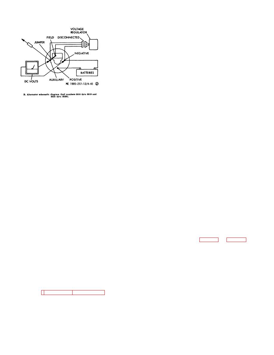
Figure 4-41.2. Alternator testing. (Sheet 2 of 8)
(a) Engine not running.
(b) Connect voltmeter across battery
CAUTION
terminals.
Do not disconnect either alternator output lead while the
(c) Connect ammeter (0-100 amp
alternator is operating.
scale) between the positive terminal of the starter
solenoid and the positive output terminal of the
CAUTION
Do not disconnect any battery cable connection while the
(d) Start engine and operate at 1000
alternator is operating.
rpm.
(e) Apply accessory load (or adjust
CAUTION
carbon pile) until ammeter reads 10.0 to 15.0 amperes.
Do not ground alternator field terminal.
(f) Allow electrical system to stabilize
(voltmeter stops changing).
CAUTION
(g) Remove the screw in the regulator
Disconnect negative battery cable prior to removing or
cover to gain access to the rheostat. Using a No. 0
installing alternator or regulator.
Phillip screwdriver, turn 1 clockwise to increase voltage
or counterclockwise to decrease the voltage until the
NOTE
voltmeter indicates the desired reading.
When doing alternator systems checks, ensure that
landing craft battery is in good condition and fully
CAUTION
charged.
Do not force rheostat beyond stops.
(2) Volt-ammeter resistance testing unit with
(h) Replace screw in regulator cover
following meter scales:
when adjustment is completed.
DC voltmeter
0-40 volts
d. Alternator Removal (fig. 4-42 and fig. 4-43) for
DC ammeter
0-10 amps, 0-100 amps
Hull Numbers 8540 thru 8560 and 8580 thru 8618.
Series Resistor
1/4 ohm
(1) Remove the alternator cover.
Field rheostat
0-50 ohm/65 watt
(2) Remove and tag electrical leads.
(3) Remove -adjustment strap bolt and move
Carbon pile
alternator as necessary to remove belt.
(4) Remove mounting bolt and remove
DC test lamp, 12 or 24 volts
Battery hydrometer
Jumper leads 2, 4, 6, 10 feet in length with alligator clips
(3) Figures 4-41.5 through 4-41.8 provides
test instructions and test schematics to fol-
4-45
|
||
 |
||