| Tweet |

Custom Search
|
|

|
||
 TM 55-1905-217-34
ME 1905-217-34/3-13
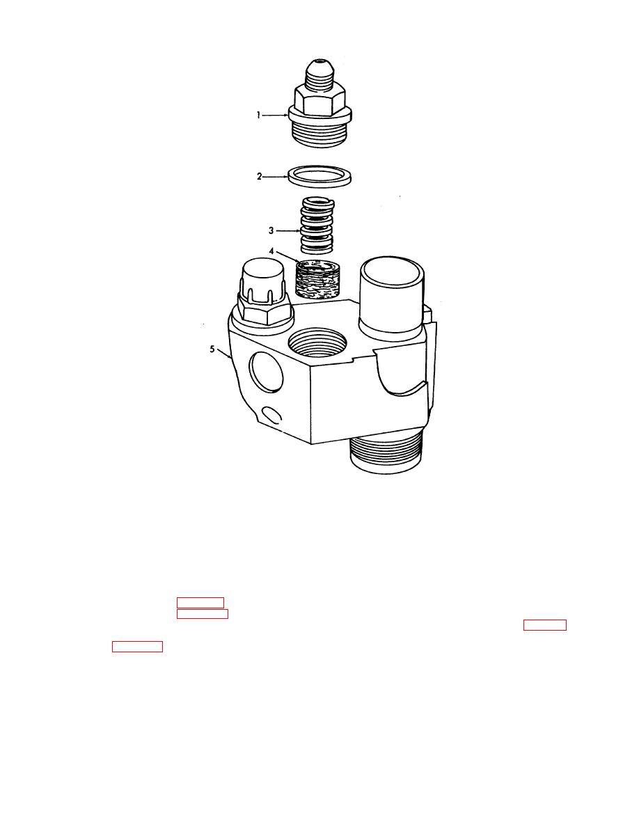
1.
Filter Cap
2.
Cap Gasket
3.
Filter spring
4.
Filter
5.
Body
Figure 3-13. Fuel injector filter, removal and installation.
(2) Refer to figure 3-8 and remove injector follower stop pin.
(3) Refer to figure 3-11 and remove injector follower, spring and plunger.
(4) Reverse the injector in the fixture, and disassemble using a deep socket, loosen nut (1, fig. 3-14) on
the injector body (15) the injector rack, gear, spray tip and valve assembly components in numerical sequence as
illustrated in figure 3-14.
3-15
|
||
 |
||