| Tweet |

Custom Search
|
|

|
||
 TM 55-1905-217-34
NOTE
The lip of the inner oil seal faces the rotors when installed in the body.
(c) Apply a thin coat of sealing compound to the outside diameter of the oil seal casing.
(d) Place the oil seal lip protector with the oil seal over the end of the oil pump drive shaft. Then, slide
the oil seal down near the protector and against the pump body.
(e) Place the oil seal installer J 6904-3 over the oil seal lip protector J 6904-2 and rest on the oil seal.
(f) Bring the ram of the press down on the installer and press the oil seal straight into the pump body
until the installer contacts the top of the oil seal lip protector.
(g) Place the second oil seal over the tapered end of the oil seal lip protector J 6904-2 with the lip of the
oil seal facing up.
NOTE
The lip of the outer oil seal points away from the rotors when installed in the body.
(h) Place the oil seal lip protector with oil seal over the end of the oil pump drive shaft. Then, slide the
oil seal down over the protector and against the pump body.
(i) Place the oil seal installer over the top of the oil seal lip protector and rest on the oil seal.
(j) Bring the ram of the press down on the installer and press the oil seals into the pump body until inner
oil seal rests on the gasket.
e. Installation. Install the transmission oil pump (TM 55-1905-217-12, para 4-70).
3-12. Power Take-Off Assembly
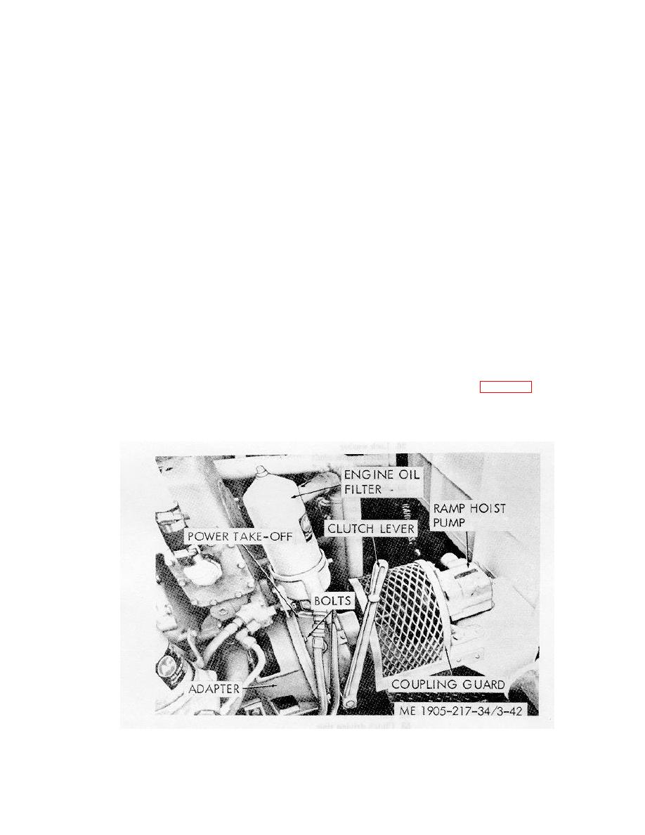
a. General. The outboard engine of each propulsion unit is equipped with a front mounted power take-off
to drive the hydraulic pumps for the ramp hoist system. Each power take-off includes a lever operated clutch.
A front end power take-off adapter supports the power take-off assembly and surrounds the clutch and drive
mechanism. The adapter retains the crankshaft oil seal and is bolted to the engine front end plate and cylinder
block.
b. Removal.
(1) Remove coupling guard and ramp hoist pump, (TM 55-1905-217-12, para 4-84).
(2) Disconnect hoses from engine oil filter and remove filter, (TM 55-1905-217-12, para 4-24).
(3) Support the weight of the power take-off assembly with a rope sling and chain hoist. Engage the
clutch with the hand lever to hold the clutch facing in place.
(4) Remove the bolts and lockwashers (fig. 3-42) securing the power take-off assembly to the front end
power take-off adapter.
(5) Screw two of the clutch housing attaching bolts into the tapped holes provided in the flange of the
clutch housing and push the power take-off assembly away from the front end power take-off adapter. Pull the
power take-off assembly straight back away from the engine.
3-59
|
||
 |
||