| Tweet |

Custom Search
|
|

|
||
 TM 55-1905-217-34
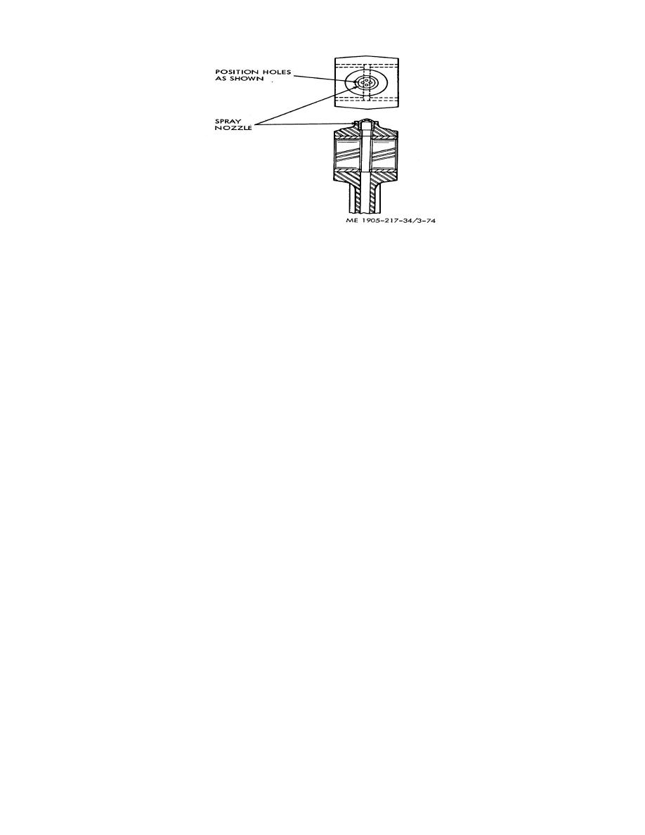
Figure 3-74. Installation of spray nozzle in connecting rod.
(b) Support the connecting rod in an arbor press. Then, place a short 3/8 inch I.D. sleeve on top
of the spray nozzle and under the ram of the press.
(c) Press the spray nozzle into the connecting rod until it bottoms in the counterbore.
(d) Install new bushings in the connecting rod.
(4) Install Bushing in Piston.
(a) Place the spacer J 1513-4 in the hole in the fixture J 1513-1.
(b) Set the piston on the fixture so the spacer protrudes into the bushing bore.
(c) Insert the installer J 1513-6 in a bushing. Then, position the bushing and installer over the
lower bushing and installer over the lower bushing bore.
NOTE
The bushing joint should be located toward the bottom of the piston.
(d) Insert the handle J 1513-2 in the bushing installer and drive and bushing in until it bottoms on
the spacer.
(e) Install the other bushing in the same manner.
(5) Ream Bushings in Piston. The piston bushings must be reamed after installation in the piston.
Proceed with reaming tool set J 3071-01 as follows:
(a) Clamp the piston bushing reaming fixture J 5273 in a vise. Then, insert the guide bushing J
3071-7 in the fixture and secure it with the setscrew.
(b) Place the piston in the fixture and insert the pilot end of the reamer J 3071-6 through the
clamping bar, piston pin bushings, and into the guide bushing.
(c) With the piston, fixture, and reamer in alignment, tighten the wing nuts securely.
(d) Ream the bushings. Turn the reamer in a clockwise direction only, when reaming or
withdrawing the reamer. For best results, use only moderate pressure on the reamer.
(e) Withdraw the reamer and remove the piston from the fixture. Remove the chips with
compressed air and measure the inside diameter of the bushings. The diameter must be 1.5025 inches to
1.5030 inches.
(6) Fitting Piston. Measure the piston diameter, cylinder liner bore, and block bore, preferable at room
temperature (70 F).
(a) The piston skirt diameter must be measured lengthwise and crosswise of the piston pin bore. The taper
and out-or-round, measured from a point approximately 1.88 inches from the top of the piston to the bottom of
the piston, must not exceed .0005.
(b) A new cylinder liner has an inside diameter of 4.2495 inches to 4.2511 inches throughout the entire length.
Therefore, with new parts, the piston-to-liner clearance will vary with the particular piston diameter. A
maximum clearance of .012 inches is allowable with used parts.
(c) Hold the piston upside down in the cylinder liner and check the piston-to-liner clearance. To avoid
inaccurate readings, the liner must be placed in the cylinder block. Check the clearance in four places, 90 o
apart.
(d) Feeler gage set J 5438 may be used for checking the piston-to-liner clearance. The set consists of a feeler
gage pack J 3174-01, a spring scale J 8129, and a swivel connection J 593-14. The spring scale, attached to
the appropriate feeler gage, is used to measure the amount of force in pounds required to withdraw the feeler
gage from between the piston and liner.
(e) Select a feeler gage with a thickness that will require a pull of six pounds to remove. The piston-to-liner
clearance will be .001 inch
3-102
|
||
 |
||