| Tweet |

Custom Search
|
|

|
||
 TM 55-1905-219-14-10
5-19.1. CAMSHAFT ASSEMBLY AND GEAR TRAIN - MAINTENANCE INSTRUCTIONS (Continued).
LOCATION
ITEM
ACTION
REMARKS
INSTALLATION (Cont)
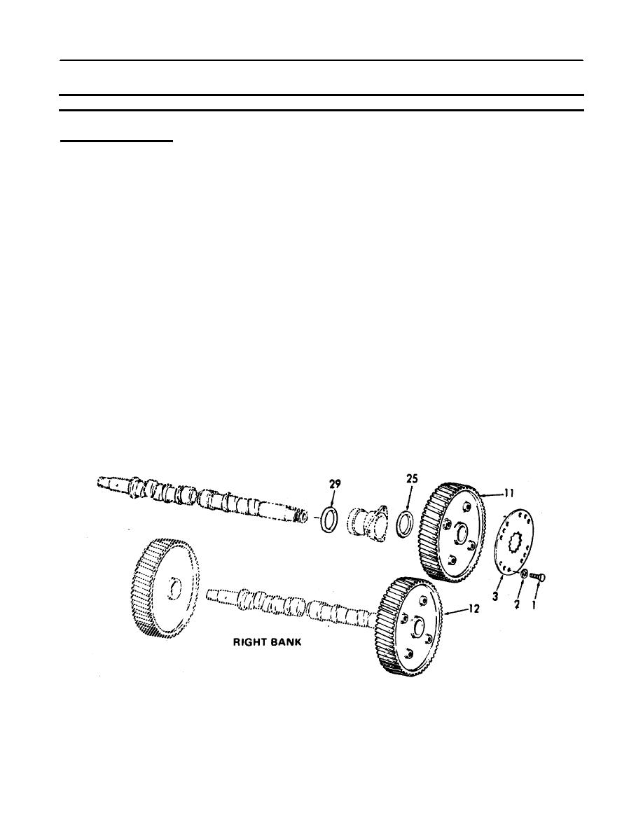
n. Retainer
1. Install.
nuts (3) ,
screws
2. Tighten screws to
(1), and
35-39 lb-ft (47.5
lockwasher
52.9 Nm) torque.
(2)
3. Remove clean cloth.
o. Thrust
Check the clearance
washers
between the thrust
(25 and
washer and the thrust
29)
shoulder of each cam-
shaft. The specified
clearance is .004" to
.012" with new parts
or a maximum of .018"
with used parts.
p. Gears (11
Check the backlash
and 12)
between the mating
gears. The specified
backlash between new
gears is .003" to
.008" or a maximum of
.010" between worn
gears.
LEFTBANK
5-342
|
||
 |
||