| Tweet |

Custom Search
|
|

|
||
 TM 55-1905-219-14-4
3-8.
MARINE GEAR - MAINTENANCE INSTRUCTIONS (Cont).
c.
Selector Valve Assembly.
(1) General. The selector valve assembly contains passages and ports for the transmission and direction of
pressurized oil within the hydraulic system. It is the function of the pressure rate control piston within the selector valve
assembly to provide a rapid, yet smooth, pressure rise for the hydraulic system when required.
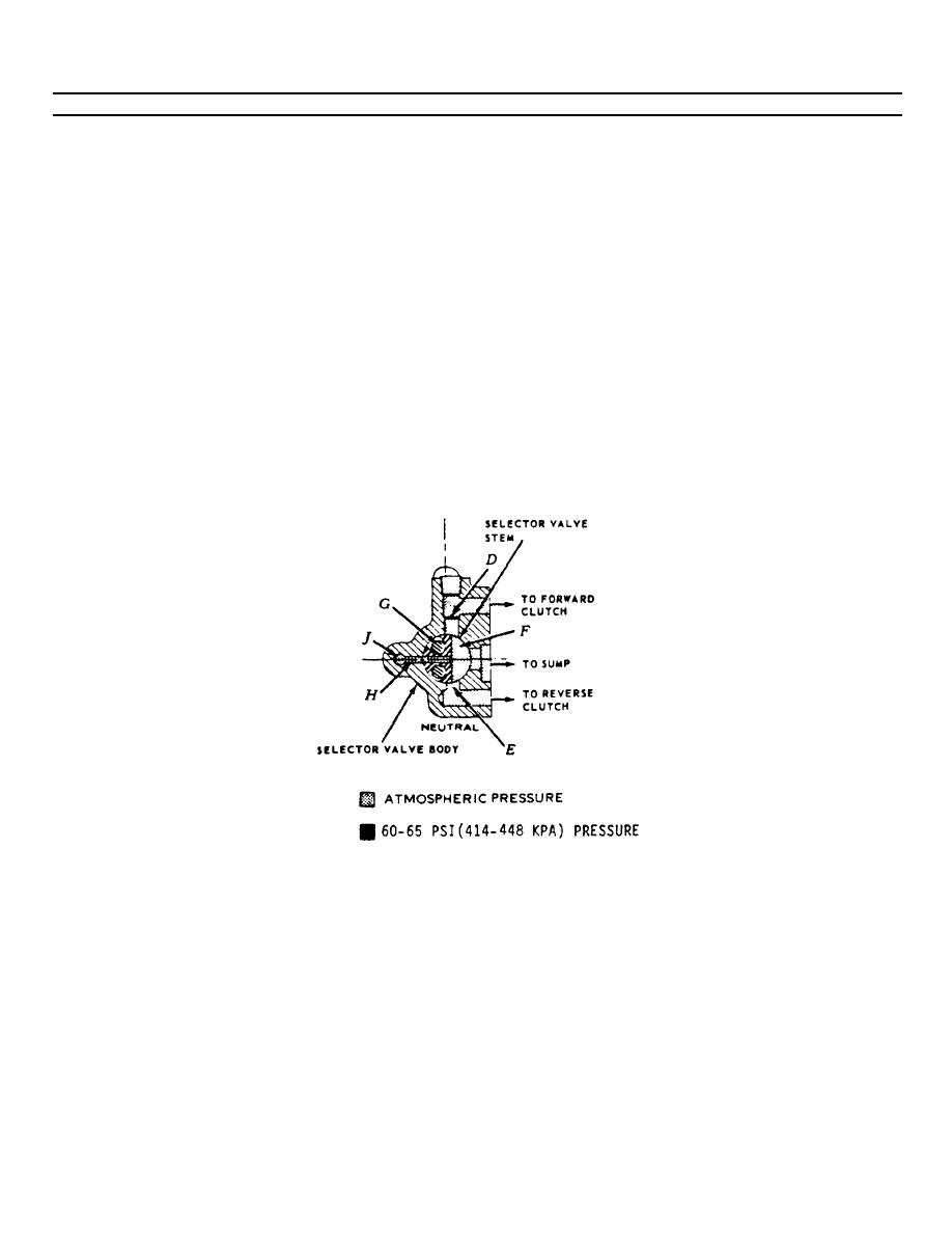
(2) Selector Valve-Neutral. Oil enters the selector valve body through passage A and fills chamber B. The oil
causes the pressure regulation piston to partially compress the piston outer and inner springs against the pressure rate
control piston. This results in an oil pressure of 60-65 psi (414-448 k pa) in chamber B. The movement of the pressure
regulation piston against the springs exposes port C in the valve body. Port C directs the pressurized oil to the oil return
pipe cavity in the front face of the selector valve body. The piston and spring in the oil return pipe regulate the cooling
and lubricating oil supply to a pressure of 18-20 psi (124-138 kpa). Passage D (which is the engaging outlet to the forward
clutch) and passage E (which is the engaging outlet to the reverse clutch) are interconnected by slot F in the selector
valve stem when in the neutral position. The slot is aligned with a drilled hole and cored cavity in the front face of the
valve body. The drilled hole and cored cavity are aligned with drilled holes that pass through the manifold and the main
housing to atmosphere. Therefore, passages D and E are at atmospheric pressure at this time. Also, passage J is at
atmospheric pressure since port H interconnects with slot F. The area between the pistons and around the springs is
vented to the sump through drilled holes in the front face of the valve body, the manifold, and the main housing. This
area is at atmospheric pressure at all positions of the valve which permits the return to sump of any leakage oil past the
3-288
|
||
 |
||