| Tweet |

Custom Search
|
|

|
||
 TM 55-1905-220-14-1
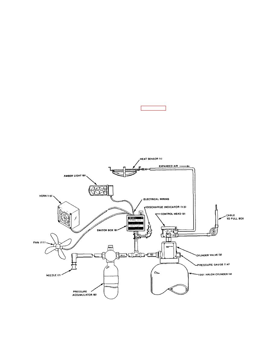
1-82. HALON SYSTEM (Cont'd).
(4) Activated valve (3) causes Halon in cylinder (4) to discharge.
(5) Discharged Halon travels through cylinder valve into pipe (5) and to pressure accumulator (6). (Pressure
accumulator serves as a delay device, allowing personnel 30 seconds to escape from room.)
(6) The Halon also enters pipe to pressure switch box (8), forcing contacts to close, thereby activating the amber
light (9), horn (10), and shuts off the fan (11). Discharge indicator (13) registers Halon discharge, and the pressure
gauge (14) registers the pressure of Halon in the cylinder (4).
(7) After fill-up in accumulator, Halon travels to nozzle (7) and empties.
(8) Manually close air intake louver covers to engine rooms, located on port side of main deck house.
c. The fire alarm panel in pilothouse operates as follows (Figure 2-15, Fire Alarm Panel).
(1) If a fire occurs in the aft engine room, amber light (1) will light.
(2) If a fire occurs in the forward engine room, amber light (2) will light.
(3) If audible alarm switch (3) is in the ON position, pilothouse horn will sound.
Figure 1-70.1. Fixed Halon Fire Extinguishing System
Change 3
1-121
|
||
 |
||