| Tweet |

Custom Search
|
|

|
||
 TM 55-1905-220-14-11
5-117. SHIP'S COURSE INDICATOR - MAINTENANCE INSTRUCTIONS (Continued).
LOCATION
ITEM
ACTION
REMARKS
OVERHAUL-TEST (Cont)
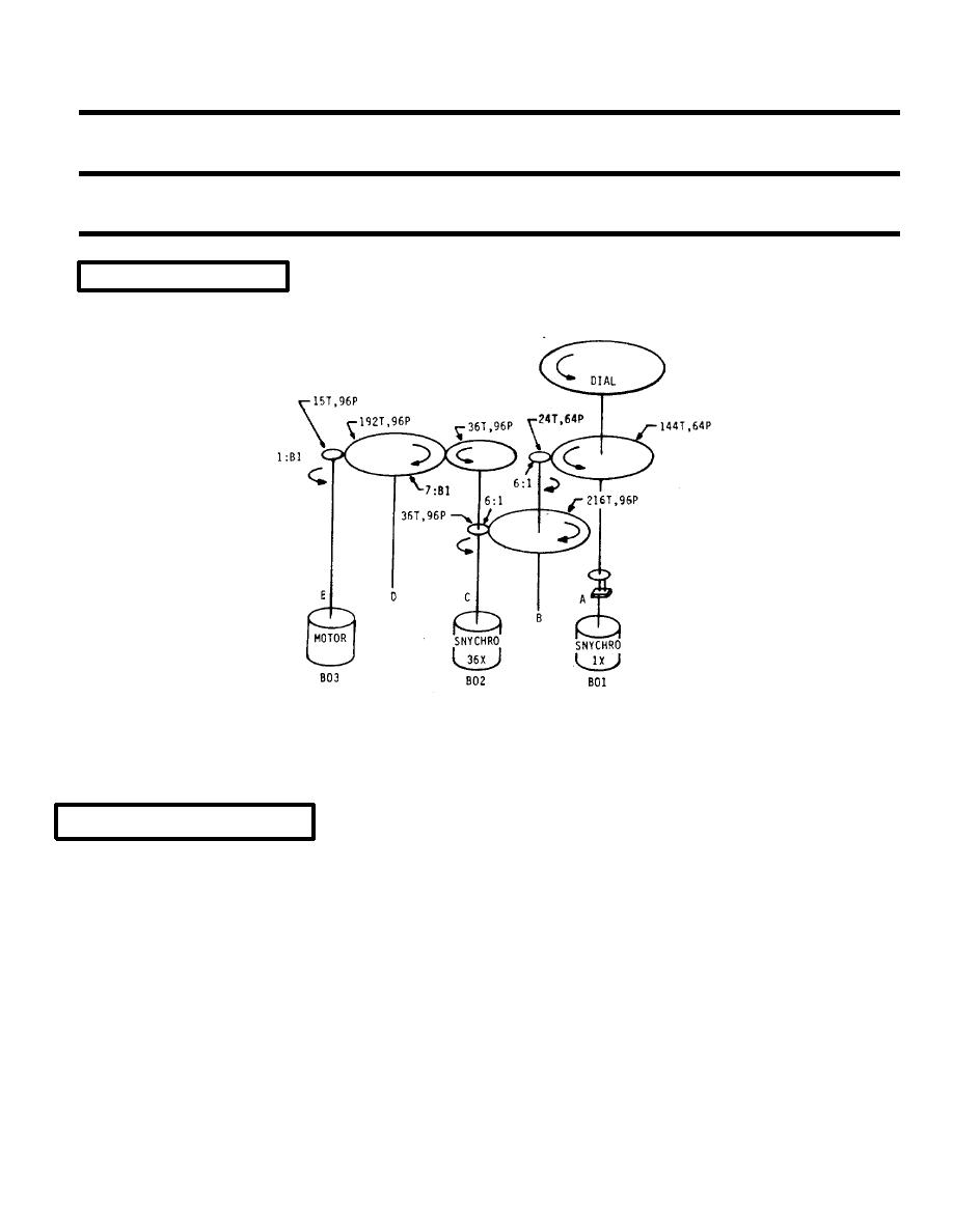
GEARING SCHEMATIC
ARROWS SHOW ROTATIONS FOR INCREASING HEADING
OVERHAUL-ADJUSTMENT
6. Zeroing of Synchro Control Transformers and Torque Receivers.
a. Energize indicator equipment. Check to see if the reading on the indicator dials correspond to those on the
synchro amplifier.
b. If it does not, deenergize the indicator, remove the cover and servo and dial assembly, re-energize, and let
the servo drive to null.
c. Measure the voltages across the R1, R2 terminals of the 1X control transformer and 36X control transformer.
They should be 2.5v (plus or minus 0.1v) and 100mv maximum, respectively. These measure- ments are obtained on a
voltmeter with an a-c sensitivity of 1000 ohms per volt. With a clean soft lint-free cloth or plastic against the accessible
teeth of the gear train, rotate the gears to drive the servo off null. It should return to null smoothly, without evidence of
friction or binding. If the gear train functions properly, but the voltages are out of line, the electrical zero adjustment is at
fault.
5-1339
|
||
 |
||