| Tweet |

Custom Search
|
|

|
||
 TM 55-1905-223-24-1
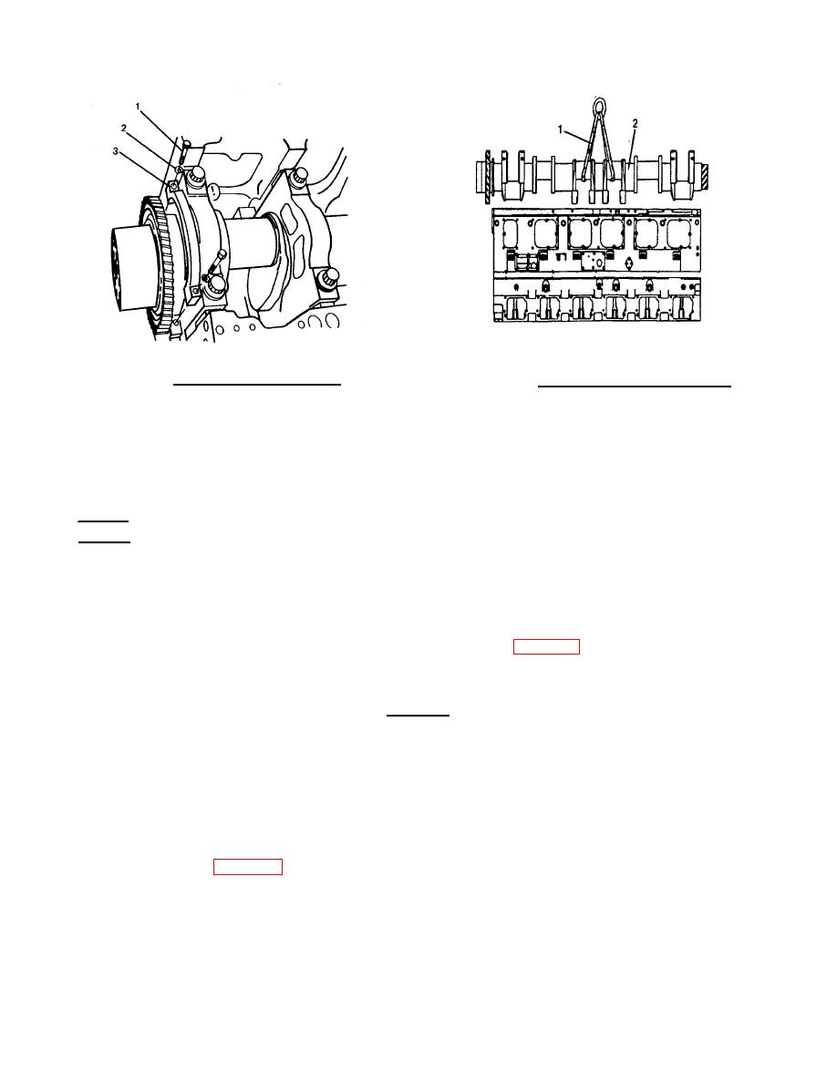
FIGURE 4-49. Main Bearing Cap Removal
FIGURE 4-50. Crankshaft Removal/Installation
NOTE
Rotate the crankshaft, if necessary, to facilitate its removal.
h.
Remove the upper main bearing shells and thrust rings. If bearing shell inspection is to be performed,
tape the upper and lower shells together or otherwise identify them as removed.
REPAIR
a.
Clean all drilled oil passages in the crankshaft with a bistle-brush and solvent (as if cleaning a rifle
r
barrel).
b.
If the crankshaft gear is chipped, cracked, broken or worn, replace the gear.
(1)
Install puller jaw and bridge assembly on crankshaft (FIG. 4-51).
(2)
Lubricate puller screw with clean engine lube oil.
CAUTION
Do not exceed 350 ft-lb (475 N ) of torque when turning the puller screw on
m
the puller jaw. The jaw will break.
(3)
Hold pry bar steady while turning puller screw with torque wrench until gear is loose.
(4)
Remove gear.
c.
Inspect visually for scratches, nicks, cracks and obvious wear patterns and measure the crankshaft
journals. See Table 4-4 .
4-45
|
||
 |
||