| Tweet |

Custom Search
|
|

|
||
 TM 55-1905-223-24-5
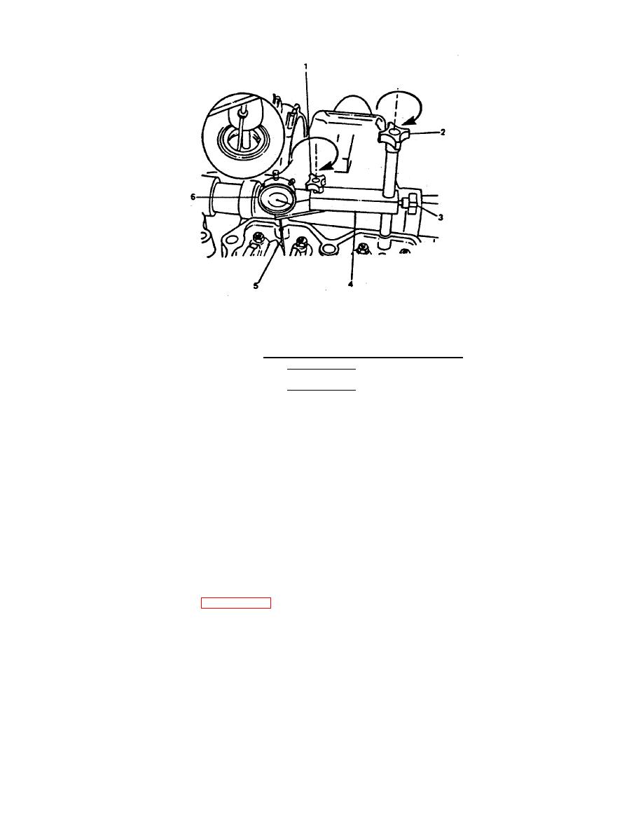
FIGURE 2-40. Installing Dial Indicator and Support .
WARNING
The injector plunger is under spring tension. Do not allow the
rocker lever actuator (P/N ST-1193) to slip. Personal injury can
result.
(g)
Use the rocker lever actuator to depress the injector plunger three or four times to make sure all the oil
and fuel have been removed from the injector assembly. Allow the lever to return slowly to prevent
damage to the dial indicator.
(h)
Actuate the lever again, and set the dial indicator at "0" (zero) while holding the injector plunger to the
bottom of its travel.
(i)
Slowly release the actuator and check the indicator travel.
(j)
The indicator travel must be 0.228 inch (5.79 mm). If not, go to step (k).
(k)
Loosen the locknut (1, FIGURE 2-41) on the injector adjusting screw.
(l)
Turn the adjusting screw (2) clockwise or counterclockwise to adjust the injector plunger to 0.228 inches
on the dial indicator reading.
(m)
Hold the adjusting screw (2) in this position. The adjusting screw (2) must not turn when the locknut (1)
is secured. Tighten the locknut (1) to 40 ft-lb torque without adapter, 35 ft-lbs with torque wrench
adapter P/N ST-669 (1).
2-121
|
||
 |
||