| Tweet |

Custom Search
|
|

|
||
 TM 55-1905-223-24-5
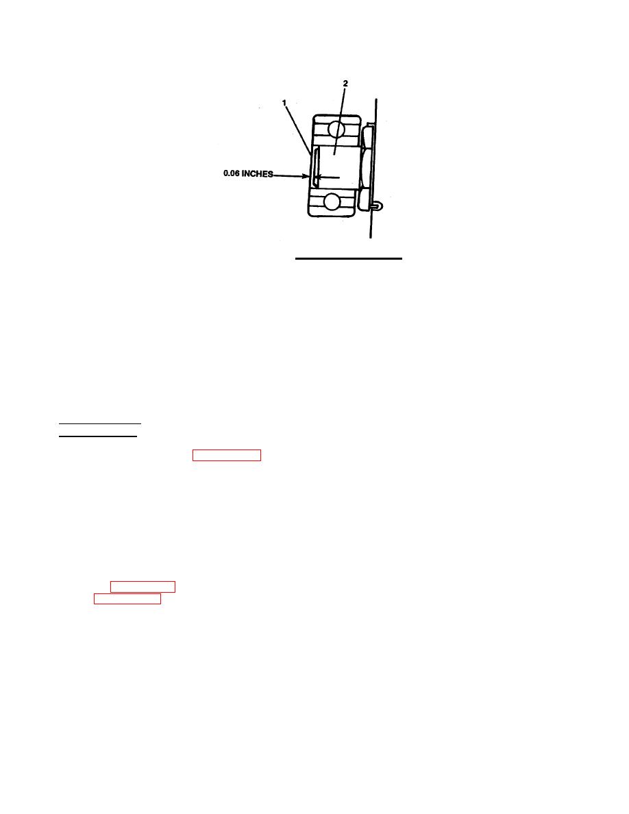
FIGURE 3-63. Bearing End Clearance.
(3)
Depress lock pin (47) with screwdriver and screw adjusting ring (46) clockwise one or two
notches or until a distinct pressure is felt when operating hand lever (34, Sheet 1).
(4)
Release adjust lock pin (47, Sheet 2) and turn adjusting ring (46) to engage nearest notch
with the pin (47).
(5)
Operate lever (34, Sheet 1) to disengage and engage the clutch a number of times to check
operation. If a distinct pressure is not felt by use of hand lever, repeat steps (3) and (4).
ao.
Position instruction plate gasket (28) and instruction plate (30) and secure with two capscrews. Tighten
capscrews to 11 ft-lb torque.
REPLACEMENT
a.
If the driving ring (1, FIGURE 3-59) was removed, install it to the flywheel with the eight capscrews.
Tighten the capscrews to 80 ft-lb torque.
NOTE
It is recommended after a new power takeoff has been assembled to an engine or
the bearings have been adjusted, to rap the shaft on the end to relieve any
preloading that may result due to the resistance of the pilot bearing when being
pressed into the flywheel.
b.
Position the clutch housing (6) against the engine flywheel housing, carefully aligning the pilot bearing
(2, FIGURE 3-60, Sheet 1) with the flywheel pilot and the clutch driving plates with the driving ring (1,
3-98
|
||
 |
||