| Tweet |

Custom Search
|
|

|
||
 TM 55-1905-242-14
0002 00
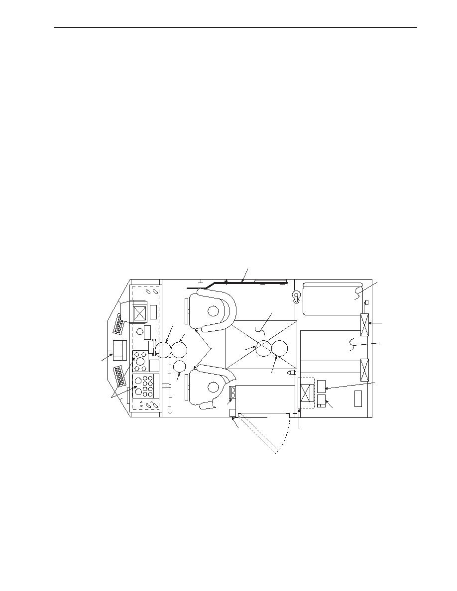
PILOTHOUSE COMPONENTS
1.
White light. Located in overhead, illuminates the pilothouse.
2.
Ramp control lever. Controls raising and lowering of bow ramp.
3.
Removable deck plate. Allows access to air conditioning equipment located under pilothouse deck.
4.
Bench seat. Provides seating at chart table. Bench seat has stowage underneath.
5.
HF/SSB radio. Provides long range communication capability.
6.
Chart table. Provides working space in aft section of pilothouse. Top of chart table raises to allow access to chart
stowage underneath.
7.
DE-ICER Switch. Permits the operator to turn ON and OFF the pilothouse windshield de-icer.
8.
GPS receiver. Provides readout of vessel's position and other navigational data.
9.
Control and distribution panel. Contains breakers that control many of the vessel's 24 Vdc electrical circuits.
10.
Comms nav aids distribution box. Contains breakers that control the communication gear and navigational aids located
in the pilothouse.
11.
Engine room fire suppression pull box. Remotely controls the discharge of FM-200 into the engine room.
12.
Red light. Located in overhead, illuminates the pilothouse.
13.
Engine room ventilation shutdown controls. T-handle controls close the engine room intake ducts in case of fire.
14.
Chairs. Provide seating for coxswain (port) and for engineer (starboard).
15.
General alarm contactor. Located on overhead. Activates general alarm.
16.
Instrument panel. Allows coxswain and engineer to monitor and control propulsion, mechanical, navigation, communi-
cation, and lighting systems.
17.
Digital compass. Provides digital readout of compass heading. Sender located on mast.
2
4
3
1
5
12
6
w
R
w
R
14
1
17
12
7
15
16
13
8
11
9, 10
PILOTHOUSE COMPONENTS
0002 00-9
|
||
 |
||