| Tweet |

Custom Search
|
|

|
||
 TM 55-1905-242-14
0105 00
REMOVAL (continued)
3.
To remove the junction box:
a.
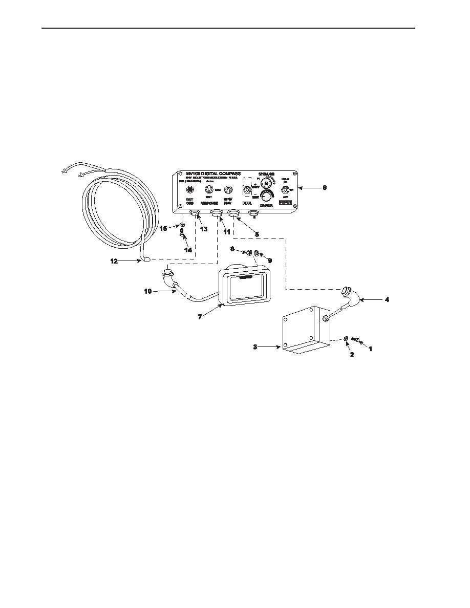
Disconnect the power cable (12) from its socket (13) on the junction box (6).
b.
Set the multimeter to the Vdc (Volts direct current) setting and check for voltage at the power cable (12). If no voltage
is noted, proceed to the next step. If voltage is noted, ensure that the circuit breaker is properly secured.
c.
If not already disconnected, disconnect the remote display unit cable (10) and the processor unit cable (4) from their
sockets (11 and 5) on the junction box (6).
d.
Remove the screws (14) and washers (15) that secure the junction box (6) to the console.
INSTALLATION
1.
To install the processor unit:
a.
Position the processor unit (3) on its mount so the arrow index is pointing forward and secure it with the bolts (1) and
lockwashers (2).
b.
If the processor unit cable (4) was removed from the processor unit (3), attach the cable to the processor unit,
leaving a strain relief loop of approximately 8" (203 mm). Securely wrap the connection with silicone tape to prevent
corrosion. Overwrap the silicone tape with three layers of electrical insulation tape.
c.
Route the processor unit cable (4) down the mast, through the bulkhead, and into the pilothouse securing it in the
same manner as the old cable.
d.
Connect the processor unit cable (4) to its socket (5) on the junction box (6).
2.
To install the remote display unit:
a.
Connect the remote display unit cable (10) to its socket (11) on the junction box (6).
b.
Route and secure the remote display unit cable (10) in the same manner as the old cable.
c.
Position the remote display unit (7) on the console.
0105 00-2
|
||
 |
||