| Tweet |

Custom Search
|
|

|
||
 TM 55-1905-242-14
0205 00
CONTROL PANEL BOOST SUPPLY REPLACEMENT
1.
Remove the screws (14) that secure the recessed controls panel (15) and the vent panel (16) to the cabinet. Remove the
recessed controls panel and the vent panel.
2.
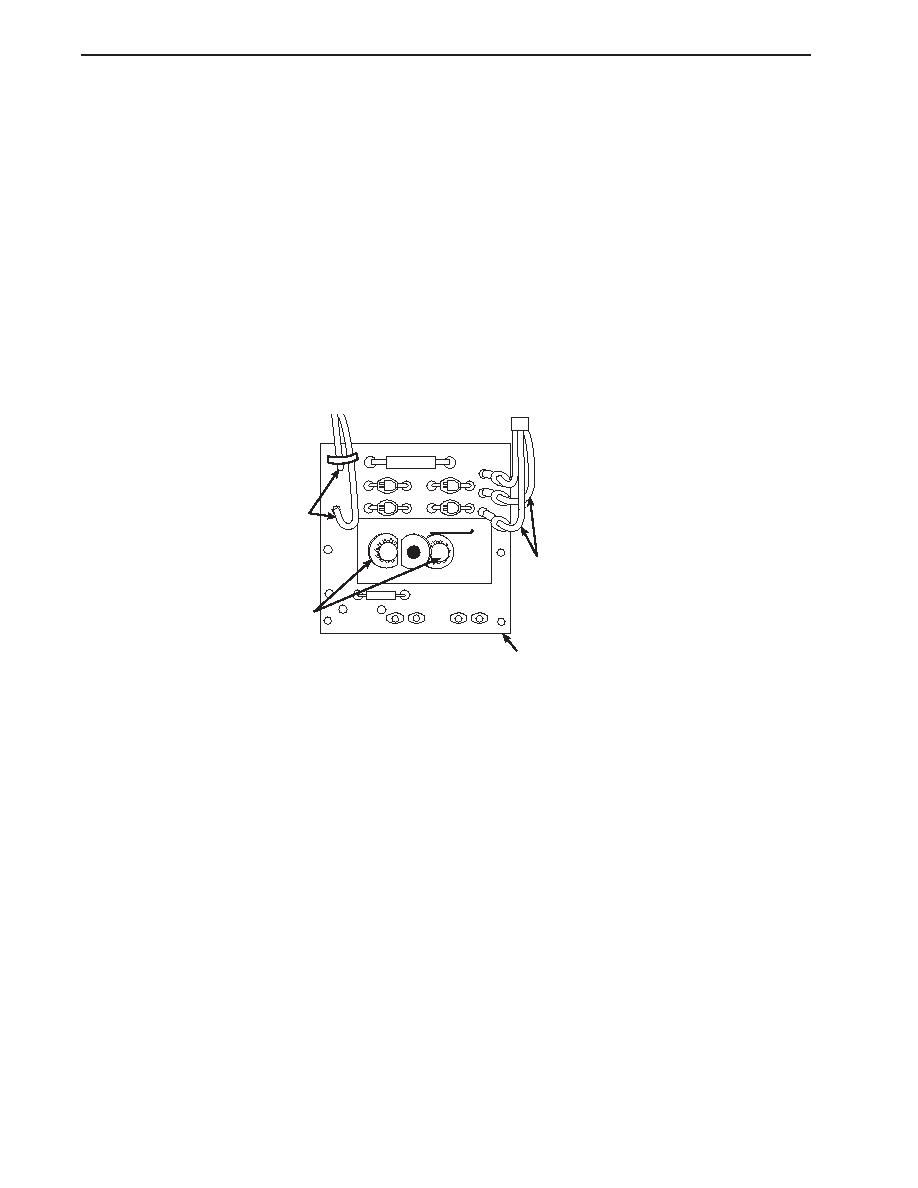
Label and disconnect the wiring (17) from the control panel boost supply (18).
3.
Remove the screws (19) that secure the control panel boost supply (18) to the cabinet. Remove the control panel boost
supply.
4.
Position a new control panel boost supply (18) in the cabinet and secure it with the screws (19).
5.
Connect the wiring (17) to the control panel boost supply (18) using the labels from step 2 of Control Panel Boost Supply
Replacement as a guide.
6.
Position the vent panel (16) and the recessed controls panel (15) on the cabinet and secure them with the screws (14).
17
MARCHE
17
19
18
TRANSISTOR POWER STAGE REPLACEMENT
1.
Remove the screws (14) that secure the recessed controls panel (15) and the vent panel (16) to the cabinet. Remove the
recessed controls panel and the vent panel.
2.
Label and disconnect the wiring (20) from the transistor power stage (21).
3.
Remove the screws (22) that secure the transistor power stage (21) to the cabinet. Remove the transistor power stage.
4.
Position a new transistor power stage (21) in the cabinet and secure it with the screws (22).
5.
Connect the wiring (20) to the transistor power stage (21) using the labels from step 2 of Transistor Power Stage
Replacement as a guide.
6.
Position the vent panel (16) and the recessed controls panel (15) on the cabinet and secure them with the screws (14).
0205 00-4
|
||
 |
||