| Tweet |

Custom Search
|
|

|
||
 NOTE
The connecting rod cap is issued as
a complete assembly, including box,
dowel, shims, bolt, nut, and
cotterpin. When new bearings are
installed it is necessary that cap and
box be scraped and lapped to give
proper clearance and face-to-face fit.
(c) Coat the connecting rod journal of
crankshaft with Prussian blue.
(d) Place the connecting rod bearing halves
on journal, and with a firm pressure on bearing halves,
rotate bearing on crankshaft one-quarter turn.
(e) Remove bearing halves from crankshaft
and inspect the blue left on bearing. If the marks do not
give indication of approximately 67 percent face-to-face
fit, scrape and lap as follows:
1. Use a scraper and remove the blue
marks from babbitt, a little at a time.
2. Replace bearing on crankshaft and
rotate as in (d) above.
3. Remove bearing and repeat step 1.
above. Repeat this process until a good face-to-face
contact is shown.
4. When both bearing halves show a
good face-to-face contact, wash crankshaft to remove
the Prussian blue.
Plug the lubrication hole in
crankshaft with a small wooden plug, cut flush with
crankshaft.
5. Apply a thin coat of medium grinding
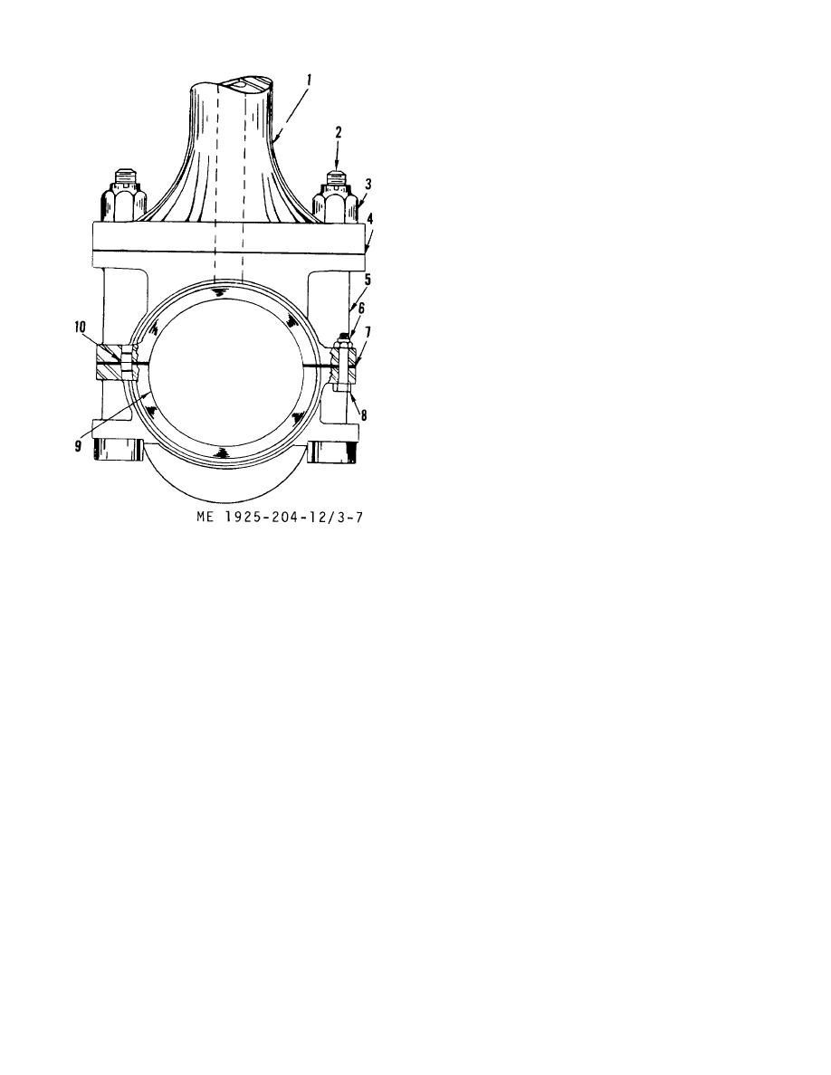
1.
Connecting rod
6. Nut
compound on crankshaft. Install connecting rod bearing
2.
Bolt
7. Shims
on crankshaft. Rotate the bearing back and forth one-
3.
Nut
8. Bolt
half turn on the crankshaft.
4.
Shims
9. Bearing cap
6. Remove the connecting rod bearing
5.
Bearing box
10. Dowel
and wash bearing and crankshaft with fuel oil, to remove
Figure 3-7. Connecting rod bearing.
the Prussian blue.
CAUTION
(5) Remove cotter pins and nuts (6) from bolt
Be sure and remove wood plug from
(8). Remove bearing cap (9).
crankshaft oil hole, to prevent
(6) Remove shims (7) and tag for proper
damage.
installation identification.
7. Position four pieces of soft lead wire
(7) Turn engine over until piston is resting on
(0.010 in. dia) on bearing cap. Secure them in place
the clamps. Continue to turn engine over slowly until
with a dab of grease.
foot of connecting rod leaves bearing box (5) then
8. Install the bearing box and cap to the
remove shims (4).
correct journal and tighten nuts to a torque of 150 ft lbs.
(8) Tag shims (4) to insure proper installation
9. Remove the bearing box and cap
thickness.
and measure the thickness of lead wires. Where the
(9) Remove bearing box (5).
thickness is between 0.003 and 0.005 in. the clearance
(10) Clean, inspect, and repair the bearings as
is correct. If clearance is less than 0.003 in., add shims.
follows:
If clearance is more than 0.005 in., remove shims.
(11) Installation of the connecting rod bearing
wipe dry. Wash off the crankshaft journal and wipe dry.
after scraping and lapping has been accomplished, is
(b) Inspect all bearing surfaces for scoring,
described in steps (12) through (15) below.
scratches, or discoloration signs of overheating.
(12) Position bearing box (5) and bearing cap
Replace defective bearings.
(9) on the correct journal, with shims (7) in place, then
install bolt (8) and nut (6). Tighten nut finger tight.
3-28
|
||
 |
||