| Tweet |

Custom Search
|
|

|
||
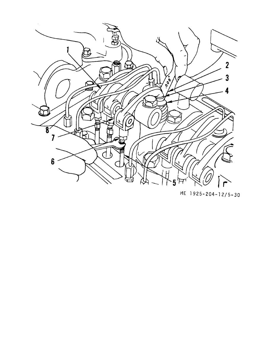
 1.
Injector rocker arm
5.
Upper push rod
2.
Thickness gage
6.
Locknut
3.
Valve rocker arm
7.
Clevis, rod end
4.
Valve stem
8.
Fuel lines
Figure 5-30. Adjusting the valve clearance.
(e) Place a 0.013 inch leaf of the thickness
(b) Stop engine and check valve clearance,
gage (2) between the valve stem (4) and rocker arm (3).
using same method as described in step (2) above, except, if
Adjust the pushrod to obtain a smooth "pull" on the thickness
the valve clearance is correct the 0.008 inch leaf of thickness
gage.
gage will pass freely through between valve stem and rocker
(f) Remove the thickness gage. Hold the
arm, but the 0.010 inch leaf will not.
push rod with a 5/16 inch wrench and tighten the locknut with
a l/2 inch wrench.
5-8. Crankshaft
(g) Recheck the clearance. At this time, if
a. General. The crankshaft is a one-piece steel forging,
the adjustment is correct, the 0.011 inch leaf will pass freely
heat treated for strength and durability. The main and
between valve stem and rocker arm, but the 0.013 inch leaf
connecting rod journals and the oil seal surfaces are induction
will not pass through.
hardened. Each main bearing journal is 3.500 inch in
(h) Check and adjust the remaining
diameter. The connecting rod journal diameter is 2.750 inch.
exhaust valves in a similar manner.
Crankshaft wear is normally associated with bearing troubles.
(3) Adjusting valve clearance-engine hot.
Therefore, when the main or connecting rod bearings are to
(a) Run the engine until water temperature
be inspected, the crankshaft should also be inspected. If the
reaches 140F.
5-36
|
||
 |
||